Creating a Barrel Roof in Home Designer
Pro
QUESTION
How do I build a barrel roof, or curved roof, in Home Designer?

Note: In Home Designer, curved roofs must be created using multiple small roof planes, however, the ability to model actual curved roof planes is a feature available in Chief Architect Premier.
A free trial version of Chief Architect Premier can be requested from the website at: https://www.chiefarchitect.com/products/trial.html
Instructions for creating curved roof planes can be located in the Chief Architect website's Knowledge Base and Training Videos.
ANSWER
Although the process for creating a barrel, or curved roof, is easier to accomplish using Chief Architect Premier, you can still create this style in Home Designer 2026 and newer, as well as in Home Designer Pro 2025 and prior using the manual roof tools.
- This article explains how to use the CAD tools to create a grid for calculating roof pitches, and how to use that information to create a barrel style roof.
- This article assumes the user is proficient in the use of Home Designer and its CAD tools, and that they understand how to draw roof planes manually.

This article will cover:
- Creating a Cross Section/Elevation View
- Setting up the Reference Grid
- Creating an Arc and "Run" Grid
- Creating a "Rise" Grid
- Setting Roof Defaults
- Drawing the Roof Planes
- Completing the Roof
For the purposes of this example, we will use a basic 26' x 40' rectangular structure.
Creating a Cross Section/Elevation View
- In the file you'd like to create this roof style in, select 3D> Create Orthographic View> Cross Section/Elevation
 and then create a view through the left-hand side of the structure.
Note: The camera angle is important for understanding X, Y, and Z coordinates, which you will need later to help automate your grid creation.
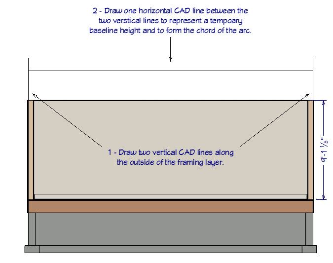
- Select CAD> Lines> Draw Line
 , then draw two lines vertically on the outside of the framing layer of each of the side walls.
These will represent the framing width of the structure, and will be used later in creation of your Rise/Run Grid.
- With the Draw Line tool still active, draw a new line horizontally, above the walls and between the two vertical lines.
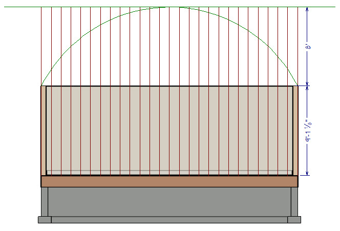
This will be used to represent the Wall Top Height and the Chord of the Arc you will create to model your barrel roof. Ultimately, this line will become the Arc itself. Your Cross Section/Elevation View may look similar to that displayed below.
You know that the Chord of the Arc will be 26' (or 312"). You have yet to determine the roof ridgeline height and the Arc Radius for your barrel roof.
Setting up the Reference Grid
Now that you have started your plan, created a Cross Section/Elevation view, and drawn in your reference lines, you are ready to begin setting up the grid.
- First, use the Select Objects
 tool to select the horizontal CAD line and use its Move edit handle to drag it down to flush with the top of the walls.
- Next, from the menu select CAD> Lines> Draw Line and draw a new horizontal cad line at some distance above the original horizontal CAD line.
- Now, select CAD> Dimensions> End to End Dimension
 , and create a dimension line between the lines representing the "Ridge Height" and the "Wall Top / Chord".
You will use this dimension to set the Ridge Height to 8' (or 96").
For information on using dimensions to set exact lengths, please see the Related Articles section below.
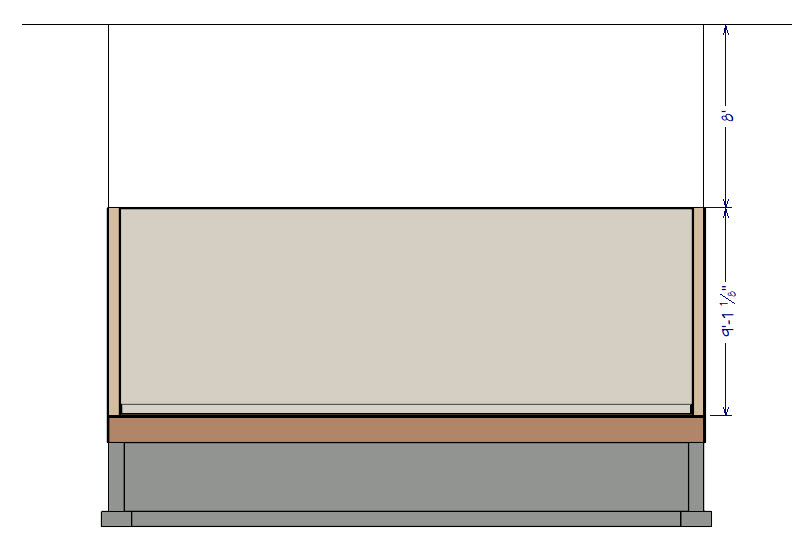
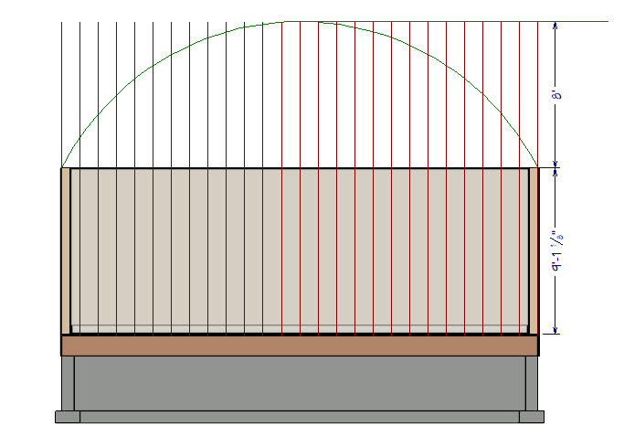
- Extend the two "Grid" lines to the new "Ridge" height line.
This line will represent the underside of the rafter framing at the "Ridge". The actual roof "Ridge" height will be approximately 96" plus the "Vertical Rafter Depth" of the first Roof Plane.
Your plan should now look like the image below.
Creating an Arc and "Run" grid
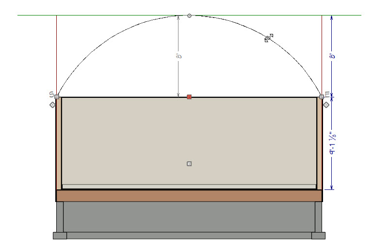
- Using the Select Objects tool, select the "Wall Top / Chord" CAD line, then click on the Change Line/Arc
 edit tool.
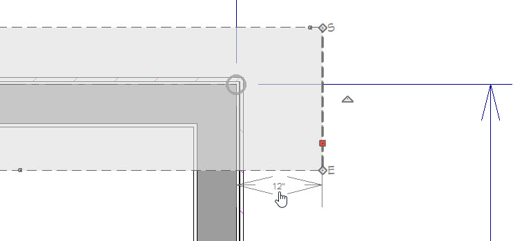
- Select the triangular edit handle located in the arc itself, then drag the Arc up the screen and snap it to the "Ridge" line.
- Next, use the Select Objects tool to select the "Grid" line on the left, then click on the Transform/Replicate
 edit tool from the Edit Toolbar.
- In the Transform/Replicate dialog:
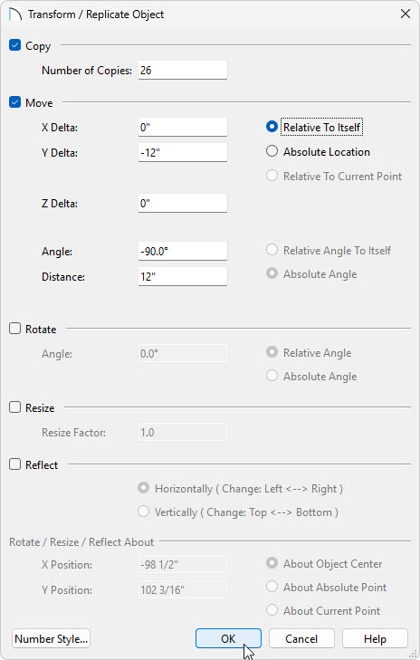
- Place a checkmark next to Copy, then set the number of copies to 26.
- Place a checkmark next to Move, then set the "Y" Delta - Move Distance to negative (minus) -12".
Since your "Run" distance will always be 12", you don't need to record this information.
- Place a checkmark next to Copy, then set the number of copies to 26.
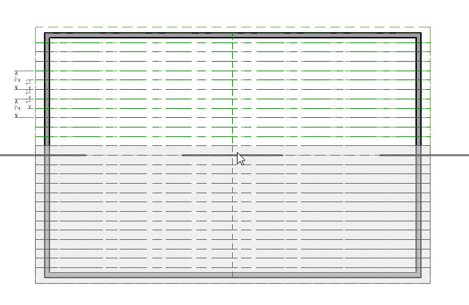
- Click OK to perform the action and close the dialog. Your Cross Section/Elevation View should now look like the image below.
Creating a "Rise" grid
Now you are ready to create your "Rise" grid.
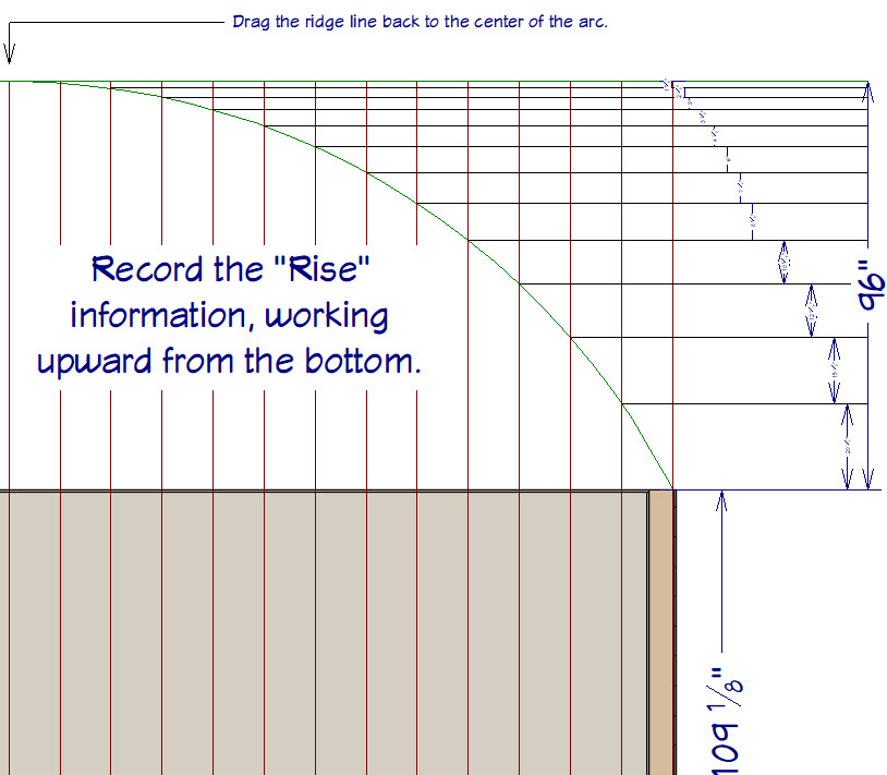
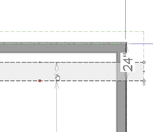
- Using the Select Objects tool, select the "Ridge" line and use the End Handle on the left to drag it from left to right to shorten it, making sure to snap it to the center of the Arc.
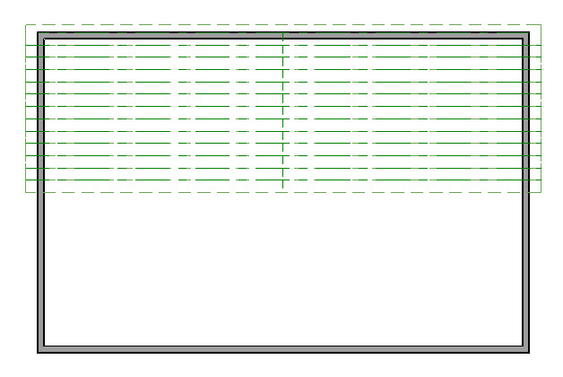
- Next, select CAD> Lines> Draw Line and draw horizontal lines to the right from the intersection points of the "Run" grid and the "Arc"
- Repeat this process for all of the intersections.
- Select CAD> Dimension> Manual Dimension
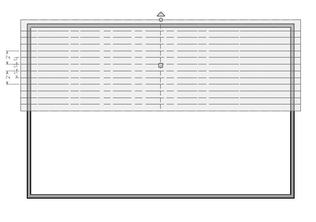
 , and draw dimensions working upward from the wall top. These will be your "Rise" dimensions.
Note: You need to record the "Rise" information for each roof segment, working from the bottom-up, for input when you create your Roof Planes. It might be easier to view these values in a different format. For information on adjusting your dimensions to show in " or "-" please see the Related Articles.
_______________
Rise Information:
01 = 20 1/4"
02 = 15 1/2"
03 = 12 9/16"
04 = 10 5/16"
05 = 8 5/8"
06 = 7 1/4"
07 = 6"
08 = 4 7/8"
09 = 3 7/8"
10 = 3"
11 = 2 1/8"
12 = 1 5/8"
13= 7/16"
_______________
Nearly all of the work you have completed to this point, has been drawn in CAD. The information you gathered will now be used to create your barrel roof. You will likely want to save this camera in case you ever need to refer back it. This can be done by having the elevation open and going to 3D> Save Active Camera ![]() . Before you get started drawing roof planes, close the Cross Section/Elevation view and return to the plan.
. Before you get started drawing roof planes, close the Cross Section/Elevation view and return to the plan.
Setting Roof Defaults
To begin, you will draw only one side of the roof, and use specific edit tools to create the other side.
- In a floor plan view, select Build> Roof> Build Roof
 .
.
You will be using the "Rise" information you gathered earlier to set each individual roof plane "Ridge" height.
- On the General panel of the Build Roof dialog:
- Set the Pitch to 20 1/4" in 12".
- Set the Eave overhang to 8".
- Set the Gable overhang to 12".
- Set the Pitch to 20 1/4" in 12".
- Click OK to implement the changes and exit the dialog without actually building the roof.
It is important that the roof pitch for any given roof plane be set prior to drawing that roof plane
Drawing the Roof Planes
- Select Build> Roof> Roof Plane
 , then click and drag out the first roof plane, being sure to draw the roof plane's baseline on the outer edge of the Framing Layer of the wall defining the rear of the structure.
If you are unfamiliar with what a Baseline is within Home Designer, click on the Help menu, and select Launch Help.
In the space provided on the Index tab, type in the keyword of Baseline and click Enter. Now click on the Roof Planes heading, which will contain a section on The Baseline.
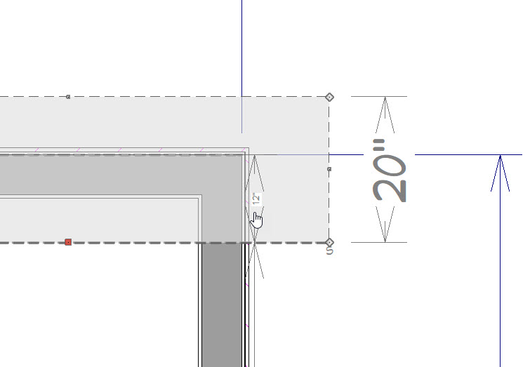
- Using the Select Objects tool, select the "Ridge" edge of the roof plane, and use the temporary dimension to position it 12" away from the baseline.
If you don't see your temporary dimension, it's likely that it's been toggled off. Temporary dimensions can be toggled on/off by going to View> Temporary Dimensions.
- Using the Select Objects tool, select one side of the new roof plane and drag it over its corresponding "Gable End". Then use the temporary dimension to set the overhang to 12".
- Do the same to the other side of the roof plane and its "Gable End".
- Before drawing the 2nd roof plane, select Build> Roof> Build Roof .
It is important that the roof pitch for any given roof plane be set prior to drawing that roof plane
- In the Build Roof dialog, set the Pitch to 15 1/2" then click OK to implement the change and exit the dialog.
- Select Build> Roof> Roof Plane , and draw the second roof plane, but be sure to draw the new roof plane's baseline on the ridge edge of the first roof plane.
- Select the "Ridge" edge of the new roof plane and use the temporary dimension to position it 12" from the "Ridge" edge of the first roof plane.
- Set the "Gable End Overhangs" to 12".
- Continue this process of changing the Pitch in the Build Roof Dialog first, then drawing each Roof Plane manually, and use the Temporary Dimensions to set the "Gable Overhangs" and Ridge edge of the new Roof Planes until the last Roof Pitch in your list has been used.
You will be at the peak of the roof when you finish.
Completing the Roof
- Select Build> Roof> Roof Plane to activate this tool, hold down the Shift key on your keyboard, then click and drag to draw a selection marquee around all the roof planes to group select them.
- Click on the Copy/Paste
 edit tool.
- You will notice that the edit tools have changed, so next you need to click on the Reflect About Object
 edit tool.
- Move the cursor to the Ridge Edge at the Peak of the roof and click on the dashed line that appears. The selected roof planes will be copied and reflected about the center Peak point of the structure.
- Select 3D> Create Perspective View> Full Overview
 to see the results.