Creating a Stair Detail in Home Designer
QUESTION
How do I create a stair detail that shows things like headroom, dimensions, and my treads?

ANSWER
You can create a stair detail by utilizing the Back Clipped Cross Section tool and the various CAD tools to notate and add detail.
In this article, we will use a single straight staircase located in a simple two story structure.
In Chief Architect Premier, a selection of pre-made stair details are available to choose from and further customize. Additionally, in Chief Architect Premier, these details can be saved to your User Catalog for future use. For more information about Chief Architect Premier, please see our dedicated Chief Architect (Professional) page.
To create a stair detail
- Navigate to 3D> Create Orthographic View> Back Clipped Cross Section
 and click and drag within your staircase to create a back clipped cross section.
With the cross section view of your stairs we can now get started on calculating and annotating the required headroom.
A stairwell will need to be created before headroom can be properly calculated. You can quickly create a stairwell by selecting your staircase and using the Auto Stairwell edit tool. More information on creating a stairwell can be found in the Related Articles section below.
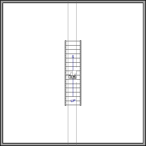
- Select CAD> Lines> Draw Line
 and starting from the nose of the first tread draw a line up your stairs, connecting to the nose of another tread.
- Select the newly drawn CAD line and click the Transform/Replicate Object
 edit tool to open the Transform/Replicate Object dialog:
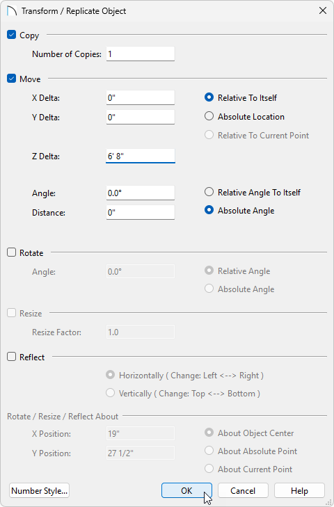
- Check the Copy box, and set the Number of Copies to 1.
- Check the Move box, ensure Relative To Itself is selected, and set the Z Delta to 6' 8".
6' 8" is the value we're using for our required head height. Use whichever value your local code requires.
- Click OK to create a copy of your CAD line 6'8" above our reference line. This line indicates our needed head height.
- Check the Copy box, and set the Number of Copies to 1.
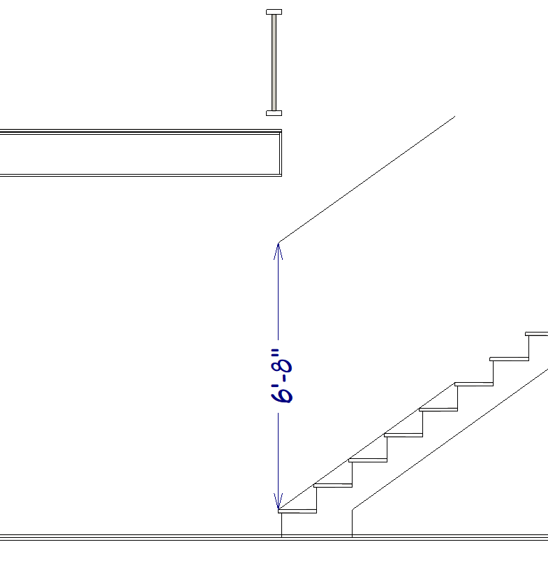
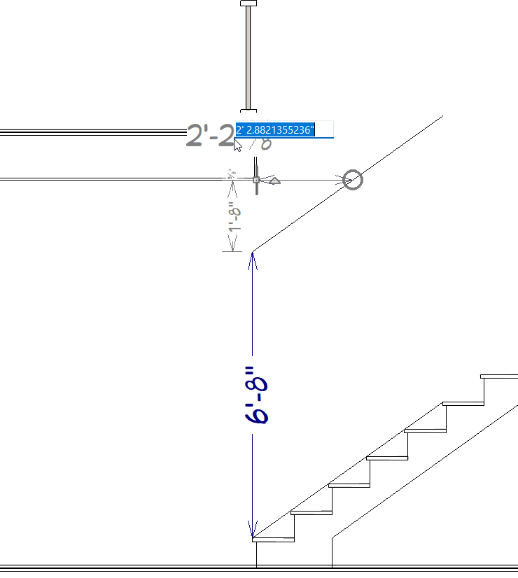
- Select CAD> Lines> Draw Line and draw a CAD line from the opening in your floor platform to the head height CAD line.
- Select CAD> Dimensions> End to End
 dimension and measure the length of this new line.
Note: You will likely receive a message that you have dimensioned to cross section lines and point markers will be used to mark these locations. Click OK to close this message, as this is expected.
- Select the CAD Marker that was placed on your floor platform and now click into the dimension to get its true value. Copy or take note of this value, as it is how far we will adjust the opening.
- Return to your floor plan view and go Up One Floor
 to Floor 2, if not there already.
- Select the railing or wall that defines your Open Below or Stairwell space and use Transform/Replicate Object edit tool to open the Transform/Replicate Object dialog:
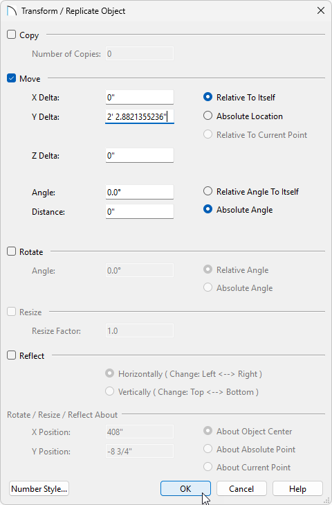
- Check the Move box and ensure Relative To Itself is selected.
- Input the value from Step 6 into either the X Delta or the Y Delta.
X Delta will move the railing left/right and the Y Delta will move the railing up/down in your plan view.
- Click OK.
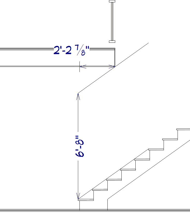
Return to your Cross Section/Elevation view and you should now see that the Floor Platform now intersects with your 6' 8" CAD line, giving you a proper head height.
- Check the Move box and ensure Relative To Itself is selected.
- Navigate to CAD> Dimensions
 and use the various Dimension tools to add your needed stair dimensions.
- Navigate to CAD> Boxes> Rectangular Polyline
 to add further detail to your cross section. Furthermore you can add a Fill Style to your polyline to create hatching or solid fills.
More information on using polylines to detail cross sections can be found in the Related Articles section below.
- Navigate to CAD> Text
 and use the various Text tools to annotate your stair detail.
- Go to 3D> Edit Active Camera
 and check the boxes for both Clip Sides and Clip Elevation. This will allow you to reduce the size of your cross section detail to only show your stairs.
More information on clipping cross section/elevation views can be found in the Related Articles section below.
Along with clipping the sides of your elevation view, after annotating your stair treads you can move your cross section camera out from the middle of the stairs to then display your railing. From you you can use the CAD tools mentioned above to annotate your railing components.
- Once you're happy with your Stair Detail, go to 3D> Save Active Camera
 to save your work.
- Once you are finished annotating your detail, go to File> Send to Layout
 to open the Send to Layout dialog:
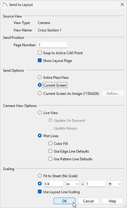
- Choose Current Screen to send only what you currently see.
- Choose Plot Lines to send over a crisp line drawing. Selecting the Color Fill option will send the detail to layout with color.
- Select the scale you'd like your detail to be in.
- Click OK to send the view to your layout.

- Choose Current Screen to send only what you currently see.