Understanding the Coordinate System
Pro | Architectural | Suite
QUESTION
I have often heard about axes and the coordinate system. What are these exactly, and how does Chief Architect/Home Designer reference them?
ANSWER
In Chief Architect/Home Designer, you can work in both 2D and 3D views. Each view uses the X, Y, and Z axes, though the Z axis is not always visible in 2D views. This article will cover how you design in relation to these axes and how you can enable the supportive coordinate system indicators to help visualize the coordinates.
Understanding the coordinate system
As you start a plan for the first time, you are presented with what is typically called a plan view. This view looks down on the plan from above -- the same view you use when reading a map. From this view you can create walls, add fixtures, create landscaping, etc.
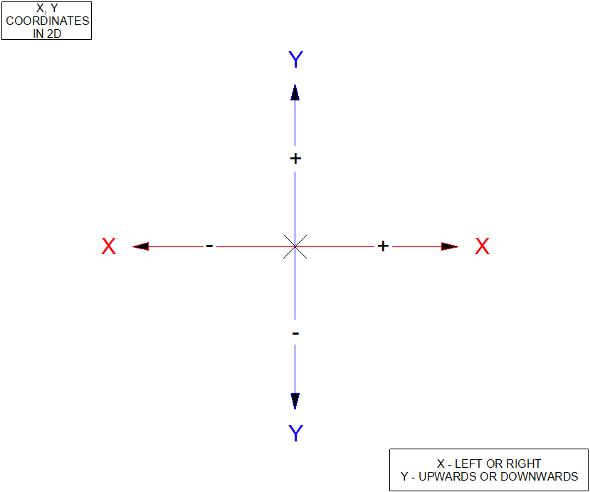
When you work in a plan view, you are employing two-dimensional drafting. In this mode, the X axis is horizontal, and the Y axis is vertical. The X and Y axis meet in the lower left corner -- an area usually called the origin. On a graph, the coordinates of this spot are called 0,0. If we move up or to the right along the X or Y axis, we are moving in a positive direction. If we move down or to the left, we are moving in a negative direction.
While not visible in the 2D plan view, the Z axis is also present. When adjusting an object's elevation, such as raising/lowering a wall cabinet, you are moving it along the Z axis. This axis will be visible in the 3D model, which is covered in the next section.
In the following illustration, the X and Y axes are detailed.
Once you have created the basis of a plan in the 2D plan space, you can create a 3D camera view to see a 3D representation of your model.
Creating a 3D view can be accomplished by navigating to 3D> Create Perspective View> Perspective Full Overview  . A 3D view of your plan will appear. From this view, a number of tasks can be accomplished.
In legacy Home Designer Suite and Home Designer Architectural navigate to 3D> Create Camera View> Perspective Full Overview  instead.
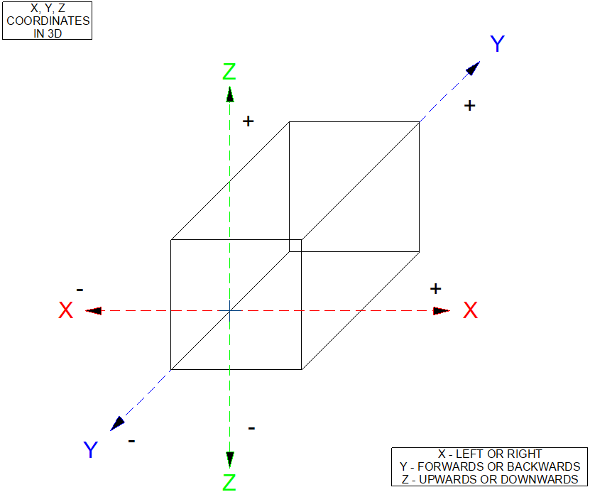
In this view, our X and Y axis have not changed. Now; however, we are able to see the model's Z axis. Again, the X axis is horizontal, the Y axis is vertical and the Z axis is perpendicular to the XY plane. The origin is still defined as the point where the X, Y, and Z axis meet.
In the following illustration, the X, Y and Z axis are detailed.
Chief Architect and Home Designer both offer optional indicators to help show these axes while you're working.
Working with and modifying the coordinate system indicators
There are three different coordinate system Indicators that can be controlled within the program through the Preferences:
-
Floating Axes Indicator
 : When enabled, it is always present in the lower left corner of a view window, regardless of the drawing space coordinates currently showing in the view.
-
Fixed Axes Indicator
 : When enabled, it is always present at the drawing space Origin: 0,0,0 (0,0 in plan views, CAD Details, and layout) and may or may not be visible in the current view, depending on its extents.
-
Origin Indicator
 : Crosshairs that are always present at the drawing space Origin (0,0).
- Navigate to Edit> Preferences
 if you're on a Windows system or Chief Architect/Home Designer> Preferences if you're on a Mac.
- Access the Coordinate System panel within the Preferences dialog. Once here:
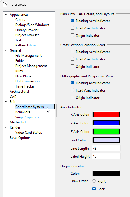
- You can check the Floating Axes Indicator, Fixed Axes Indicator, and Origin Indicator checkboxes to enable/disable these indicators in the various types of views.
Note: These indicators can also be enabled/disabled any time in a given view by accessing the View menu and selecting the appropriate indicator.
- Underneath the Axes Indicator section, you can control the Colors, Line Length, and Label Height for both the Floating Axes Indicator and the Fixed Axes Indicator.
- Underneath the Origin Indicator, you can control the Color and Draw Order for the Origin Indicator.
- You can check the Floating Axes Indicator, Fixed Axes Indicator, and Origin Indicator checkboxes to enable/disable these indicators in the various types of views.
- Click OK to save your changes.