Showing Demolition Walls in a Plan
Pro | Architectural | Suite
QUESTION
I'm working on a remodel, or addition, and I need to show the demolition walls in the plan. How can I differentiate the demo walls, or walls to be removed, from the other walls?

ANSWER
There are two methods to show demolition walls in a plan: using CAD polylines and using the Wall Hatching tool.
CAD polylines work well for showing demolition walls in a plan view, especially in instances where you may not want to see these particular walls in 3D camera views. However, this is a manual process that requires additional effort in comparison to the Wall Hatching tool. We will discuss both methods of showing demolition walls in this article.
To show demolition walls using CAD polylines
- Navigate to CAD> Draw Polyline
 from the menu.
In Home Designer Pro, navigate to CAD> Boxes> Rectangular Polyline instead.
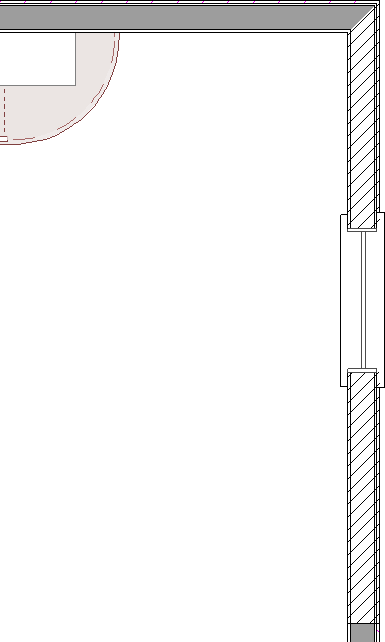
- Draw a CAD polyline over the top of the wall(s) you want to demolish, snapping to the sides of the wall.
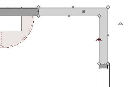
- With the polyline selected, use the Add Break
 edit tool to add additional edit handles, allowing you to shape the CAD polyline around a corner, like shown in the image above.
- Leave spaces for doors and windows, if desired.
- With the polyline selected, use the Add Break
- With the CAD polyline still selected, click the Open Object
 edit tool.
- In the Polyline Specification dialog that displays:
- On the Line Style panel, specify the Color and Style of the lines that make up the CAD polyline.
In this example, these are unchanged.
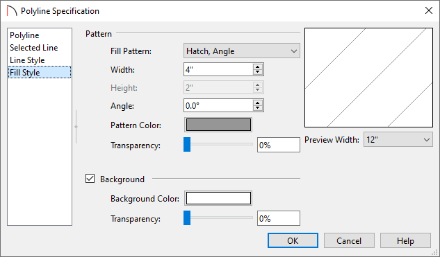
- On the Fill Style panel, specify your desired properties, such as the Fill Pattern, Width, Pattern Color, Background, and more.
In this example, the "Hatch, Angle" pattern with a Width of 4" and a dark gray color are specified.
- Once your desired changes have been made, click OK.
- On the Line Style panel, specify the Color and Style of the lines that make up the CAD polyline.
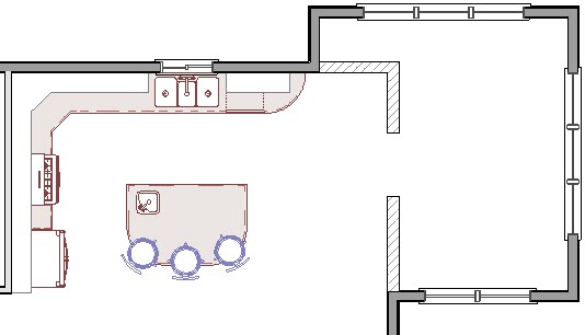
- Using the Select Objects
 tool, select the wall(s) that will be demolished, then either Delete
  or Move
  the walls from under the CAD polylines.
If you have trouble selecting the walls instead of the polylines, click the Select Next Object edit button on the toolbar, or press the Tab key on your keyboard, to cycle through nearby objects.
- Other details, like windows, can be drawn in with additional CAD lines by navigating to CAD> Draw Line
 from the menu.
In Home Designer Pro, navigate to CAD> Lines> Draw Line instead.
- You can now copy these CAD polylines to other areas of your plan using the Copy/Paste
 edit tool, or by accessing the Copy
  and Paste
  tools located in the Edit menu.

To show demolition walls using the Wall Hatching tool
- Navigate to Build> Wall> Wall Hatching
 from the menu.
Note: If only part of a wall is being demolished, it's important to use the Add Break edit tool to break the wall into separate segments before using the Wall Hatching tool.
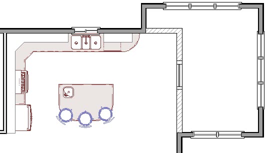
- With the tool selected, click on an existing wall to apply a hatch pattern to the wall.
- To edit the hatch pattern, click onto the wall again using the Wall Hatching tool to select the wall hatching object, then click on the Open Object
 edit button.
If the Wall Specification dialog appears instead of the Wall Hatching Specification dialog, close the dialog and attempt to open the wall hatching object again. You can see what object is selected by looking towards the bottom left corner of the Status Bar, which is located at the bottom of the Home Designer window.
- In the Wall Hatching Specification dialog that displays:
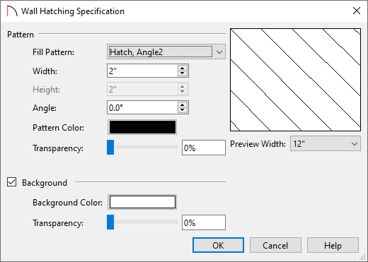
- Specify your desired properties, such as the Fill Pattern, Width, Pattern Color, Background, and more.
In this example, the "Hatch, Angle2" pattern with a Width of 2" and a black color are specified.
- Once your desired changes have been made, click OK.
- Specify your desired properties, such as the Fill Pattern, Width, Pattern Color, Background, and more.
- You can now copy the hatching to other areas of your plan using the Copy/Paste edit tool, or by accessing the Copy and Paste tools located in the Edit menu.
Note: In Home Designer Pro, Wall Hatching Defaults are available, allowing you to set specific default properties for the Wall Hatching tool.