Creating HVAC Plans
Pro | Architectural | Suite
QUESTION
How can I create HVAC plans in my Home Designer program?
ANSWER
There are a number of tools that you can use to create HVAC (Heating, Ventilating and Air Conditioning) or climate control plans in 2D, 3D and elevation views.
To add HVAC fixtures
-
Open
 the plan in which you would like to create HVAC plans and select View> Library Browser
  from the menu.
- Navigate to the Mechanical, Electrical, Plumbing folder.
- Beside each of these main categories you will see an arrow sign. Click on this to expand that category and view its contents.

- Browse to a symbol that you wish to place in your plan, such as an AC Unit, Radiator, Furnace or Register.
- Click on the symbol's name in the tree list or its image in the preview pane to select it, then click in the drawing area to place the symbol at that location.
Once your HVAC fixtures are in place, you can add ductwork if you wish. Ductwork can be represented using either 2D CAD lines that display in floor plan view only or actual 3D objects that can display in both 2D and 3D views.
To represent ductwork using 2D CAD lines
- Select CAD> Draw Line
 from the menu, then click and drag to draw CAD lines where you want the ducting in the plan. When the end of one CAD line is positioned to meet the end of another line, they will snap together to form a polyline.
- Like other objects in Home Designer, CAD lines and polylines can be moved, resized and reshaped using their edit handles.
- You can specify the color and line style of a line or polyline on the Line Style panel of its specification dialog: Click on the polyline to select it, then click the Open Object
 edit button to open this dialog.
If you choose to use polylines, be aware that they will not be visible in 3D or cross section/elevation views. If you need to model the ductwork in 3D, you can use Geometric Shapes from the Library Browser.
To model ductwork in 3D views
- Select View> Library Browser
 from the menu, then browse to the Shapes folder.

The Open Front & Back geometric shape can be used for rectangular ducting, while Horizontal and Vertical Cylinders can be used for circular ducts.
- Geometric shapes can be moved and resized like other objects in the program. They cannot be snapped together like CAD lines, however.
- Once an object has been added to your plan, you can click on the Select Objects
 tool to select it, then click on the Open Object edit button to open its specification dialog.
- On the General panel of the object's specification dialog, you can define the Height, Width, Depth and Floor to Bottom height for the selected object.
- On the Materials panel, you can change from the default material to assign it a more suitable material, such as "Metal Aluminum (Dull)," by clicking on the Select Material button.
- Click OK to apply these changes and close the dialog.
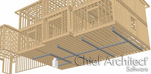
- Navigate to 3D> Create Camera View> Framing Overview
 .
.
In Home Designer Pro, navigate to 3D> Create Perspective View> Perspective Framing Overview.
- Select Tools> Display Options
 from the menu and turn on the display of the "Fixtures, Interior" and the "Geometric Shapes" layers to see your HVAC in the Framing Overview .