Modeling a Crawl Space
Pro | Architectural | Suite
QUESTION
I need to model a crawl space under my structure in Home Designer. How can I do that?

ANSWER
Modeling a crawl space in Home Designer can be easily done by setting the appropriate wall height when you build your foundation, and using terrain features.
To build the foundation
- First, launch your Home Designer software program and Open
 the plan in which you would like to create your crawl space.
- Select Build> Floor> Build Foundation
 from the menu.
- In the Build Foundation dialog, select the Walls with Footings foundation type and set the Wall Height for the height of your crawl space.
In Home Designer Pro, The Wall Height is called the Minimum Height, and it's located under the Stem Walls section.
For the purposes of this example, we used 48".
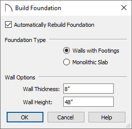
Note: If the foundation's Wall Height is less than 76" (1900 mm), an automatic slab floor will not be created.
- Click OK to generate and display the foundation level.
- Use the Select Objects
 tool to select a foundation wall and click on the Open Object
  edit tool.
- On the Materials panel of the Foundation Wall Specification dialog that opens, specify an appropriate material for the Exterior and Interior Wall Surface using the Select Material button.
For the purposes of this example, we used the Blocks Running Bond material, which can be found by navigating to Home Designer Core Catalogs> Materials> Masonry and Stone> Blocks.
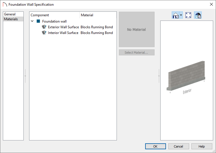
- Click OK to apply this change.
- Repeat this procedure for each foundation wall so all of the materials are the same.
To create a terrain feature
- With all the foundation walls in place, create a terrain by going to Terrain> Create Terrain Perimeter
 .
.
- Using the Select Objects tool, click on the terrain perimeter, then on the Open Object edit tool.
- Remove the check for the Hide Terrain Intersected by Building setting, then click OK.
Note: You can also remove the check in the Automatic box if you would like to specify a custom value for the Subfloor Height Above Terrain field. Please see the Related Articles section below to learn about how the structure's height relates to the terrain.
- Navigate to Terrain> Feature> Rectangular Terrain Feature
 , then left-click and drag to create a rectangle. This rectangle will serve as the crawl space dirt.
If necessary, use the Reference Display found under Tools> Floor/Reference Display> Reference Display to show another floor's information.
- Once the rectangle is drawn, use the various edit handles to reshape it to your needs. You can also use the Break
 and Change Line/Arc
  edit tools to customize the terrain feature further.
- Using the Select Objects tool, click on the terrain feature, then click the Open Object edit tool.
- On the General panel, adjust the Terrain to Top and the Thickness of the feature.
- On the Materials panel, select an appropriate material for your crawl space floor to give it the look of dirt or a plastic vapor barrier.
- On the General panel, adjust the Terrain to Top and the Thickness of the feature.
- Once all desired changes have been made, click OK, then take a Camera
 view to see the results.
You may notice when you initially take a camera view that it actually displays in the room above the crawl space area, because of the default Height Above Floor value set for your camera.
To adjust the camera
- To lower the camera, select the Move Camera Down tool by going to 3D> Move Camera> Move Camera Down
 .
.
Pressing the D key on your keyboard will move the camera downwards in a 3D view, along with U for Up, L for Left, R for Right, B for Backwards, and F for Forwards.
- Alternatively, you can also select Window> Tile Vertically
 to see both your 2D floor plan view and 3D camera view.
- Once the two views are tiled, click within the 2D floor plan view and then click once more on the camera to select it.
-
With the camera selected, click the Open Object edit tool to display the Camera Specification dialog and lower the Height Above Floor value so that it will correctly view the crawl space area.
- Once the two views are tiled, click within the 2D floor plan view and then click once more on the camera to select it.