Creating a Structure that is Built on Piers
Pro | Architectural | Suite
QUESTION
I am designing a house in an area that gets flooded and I need to build up on piers. How can I design a house that sits on piers or pilings using Home Designer?

ANSWER
Many local building codes require that houses built on flood plains be built a certain height above flood stage. Typically, this requirement is met by building on piers or pilings. To create a house on piers, follow the steps outlined in this example:
To build a house above ground level
In most situations, it's best to draw the first floor of a house plan on Floor 1 in the program. However, in the case of a house on piers, the first floor will actually be an open area in which you will place piers to support the structure above.
- To start, select Edit> Default Settings
 from the menu.
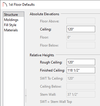
- In the Default Settings dialog, expand Floors and Rooms, expand Floor Levels, click on 1st Floor to highlight it, then click on the Edit button to display the Floor Defaults dialog for Floor 1.
- On the Structure panel of the 1st Floor Defaults dialog, specify a Finished Ceiling height of 10' (120"). This will raise the bottom of the floor platform for the first floor in your house 10' above the ground.
- Click OK to close this dialog, then click Done to close the Default Settings dialog.
- Next, select Build> Floor> Build New Floor
 .
.
- When prompted to derive the new floor from the plan below, click OK.
- In the 2nd Floor Defaults dialog that opens, set your Rough Ceiling height to the ceiling height of your living space, and click OK.
- As nothing has been drawn on Floor 1, the result will be a blank Floor 2.
- When prompted to derive the new floor from the plan below, click OK.
- Select Build> Walls> Exterior Wall
 from the menu, then click and drag the exterior walls of your plan, drawing in a clockwise direction.
- Use temporary dimensions and/or the Dimension
 tools to help you position the walls precisely. When you are satisfied with the placement of the exterior walls, it's time to place piers beneath them.

To place piers beneath the elevated floor plan
Once your floor plan is done on Floor 2, you can insert piers on Floor 1 to support it.
- To return to Floor 1, select Tools> Floor/Reference Display> Down One Floor
 from the menu.
- In order to place the piers in the correct locations under the walls above, you need to turn on the Reference Display. Select Tools> Floor/Reference Display> Reference Display
 from the menu. The outline of the walls created on Floor 2 will now display as red lines on Floor 1.
- You now need to create piers using one of the geometric shapes found in the Library Browser. Select View> Library Browser
 to open the Library Browser window and navigate to Home Designer Core Catalogs> Shapes. In this example, the Vertical Cylinder is used, although the Closed box, or perhaps one of the Pedestals or Columns from the Home Designer Core Catalogs> Architectural> Millwork catalog could also work.
- Using the red lines of the Reference Display as a guide, click at a corner of your exterior walls to place a pier at that location. If you need to adjust the pier's location, click on it to select it and move it using the Move
 edit handle that displays at the object's center.

- With the pier still selected, click the Open Object
 edit button to open the Geometric Shape Specification dialog. On the General panel:
- Specify the desired Height of your pier. In most cases, this will be the default ceiling height of Floor 1, specified in the first part of this article.
- Specify the Width and Depth of your pier. These values correspond to the cylinder's diameter and will be the same in most instances.
- Specify the desired Height of your pier. In most cases, this will be the default ceiling height of Floor 1, specified in the first part of this article.
- Then, on the Materials panel:
- Click on the indented line, then click the Select Material button.
- In the Select Material dialog, go Home Designer Core Catalogs> Materials> Concrete> Smooth.
- In the Smooth sub-folder of the Concrete folder, click on a concrete material to select it and click OK to return to the Geometric Shape Specification dialog.
- Click OK to close the Geometric Shape Specification dialog and apply your change.
- Click on the indented line, then click the Select Material button.
- Select 3D> Create Camera View> Elevation
 from the menu and click and drag a camera arrow perpendicular to either wall above the new pier.
In Home Designer Pro, use 3D> Create Orthographic View> Cross Section/Elevation.
- In the Elevation view, click on the pier to select it and use the Move edit handle that displays at its center to adjust its location so that it lines up correctly with your main structure.
- Use the top edit handle to make any needed adjustments to the height so that it meets the bottom edge of the wall above.
- If you have trouble viewing the pier, select Window> Zoom
 from the menu and click and drag a rectangle around the part of the view that includes the pier and the wall above. The program will zoom in to fill the view window with the contents of that rectangle, allowing you to edit the pier more easily.
- When you are satisfied with the appearance of your pier, select File> Close View to close the Elevation view and return to floor plan view.

- In the Elevation view, click on the pier to select it and use the Move
- Now that the pier has the correct material and size specifications, you can make copies of it and place them around the plan as needed.
- In floor plan view, click on the pier to select it, then click the Copy/Paste
 edit button, and then click the Sticky Mode
  edit button. Your cursor will now display the Copy/Paste
  icon. Clicking the Sticky Mode tool after selecting Copy/Paste allows you to paste as many copies as you like, rather than just one.
- Click at a location that needs a pier to place one there, then continue clicking until all needed piers have been created around the perimeter and in the middle of the plan as appropriate for your design.
- Do not worry about placing them precisely at this time as they can be positioned more accurately and height adjusted if you have uneven terrain in a moment.
- When you are finished pasting copies of your pier, disable the Paste function by clicking the Select Objects
 tool.
tool.
- In floor plan view, click on the pier to select it, then click the Copy/Paste
- You can use the End to End Dimension
 and the Center Object
  tools to position your piers accurately. Slide the piers to the end of the walls using the Move edit handle.

- When the piers are in their correct positions, the dimension lines can be deleted.

To create stairs that reach the ground
With the house elevated on piers, you can now create stairs from the floor to the ground. Normally, stairs generate from the current floor upwards to the floor above and snap precisely to both floor heights. When stairs are built from a floor to the ground, a different approach can be used.
- Select Tools> Floor/Reference Display> Up One Floor
 from the menu to go the Floor 2.
- Select Build> Stairs> Draw Stairs
 from the menu, then hold down the Alt key on your keyboard and click and drag to create a stairway. Holding Alt while you draw stairs directs the program to draw them in a downward direction rather than upward.
- When you release your mouse button, a warning message will caution you about drawing stairs in a downward direction. Click OK to close the message box.
- To create a landing between two runs of straight stairs, create the stair sections as described above, leaving a space between them where you would like a landing.

- With the Draw Stairs tool selected, click once in the landing area to create a landing that joins the two stair sections.

- Select Build> Door> Hinged Door
 and then click on the wall at the top of your staircase to place a door.
- Select 3D> Create Camera View> Perspective Full Overview
 from the menu to view your elevated house on a pier foundation.
In Home Designer Pro, use 3D> Create Perspective View> Perspective Full Overview.