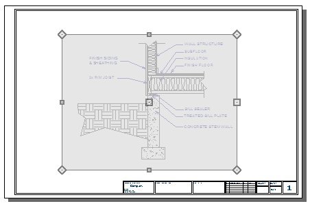
Creating a Cross Section Detail in Home Designer
QUESTION
I need to create a cross section detail in Home Designer. How do I do this?

ANSWER
In Home Designer 2026 and newer, as well as in Home Designer Pro 2025 and prior, the CAD, Text, and Dimension tools can be used to create a cross section detail of your structure.
In this article, we will cover the following topics to create a foundation detail:
- Creating a cross section view
- Adding fill styles
- Adding break lines
- Adding text
- Aligning text objects
- Sending the detail to layout
- Cropping the view on the layout page
To create a cross section view
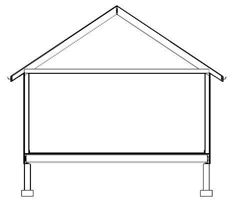
- Select 3D> Create Orthographic View> Back Clipped Cross Section
 , then click and drag a camera arrow in the direction that you want the view to show. The camera arrow, or line of sight, should be perpendicular to the desired cross section plane.
Note: The Back Clipped Cross Section tool includes only the objects between the starting point and stopping point of the cross section line.

- Select Tools> Display Options
 from the menu and in the Layer Display Options dialog that opens, turn on or off any layers, as needed.
Note: If you wish to display framing in your cross section detail, remember that you must first build the framing. Please see the Related Articles section to learn more.
- Select View> Color
 from the menu to toggle colors on or off.
-
Zoom
 in on the area that you wish to detail.
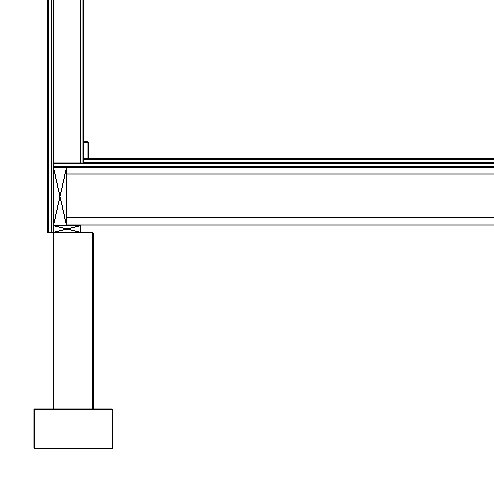
- Select 3D> Save Active Camera
 from the menu.
Now we are ready to add CAD items, labels, and dimensions.
To add fill styles
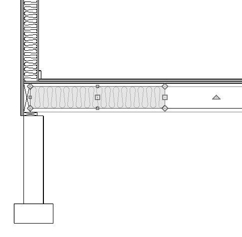
- Select CAD> Boxes> Insulation
 , then click and drag to draw a rectangular shape with an insulation fill.
- If you have Object Snaps
 enabled, Insulation Boxes will snap to the edges of floor framing and wall framing.
- Insulation Boxes can also be resized using their edit handles and dimensions.
- If you have trouble getting the correct size, hold down the Ctrl/Command key to allow for free movement.
- Note that Boxes, Cross Boxes, and Insulation must always be rectangular in shape.
- If you have Object Snaps
- Select CAD> Boxes> Rectangular Polyline
 from the menu, then click and drag to draw a closed rectangular shape.
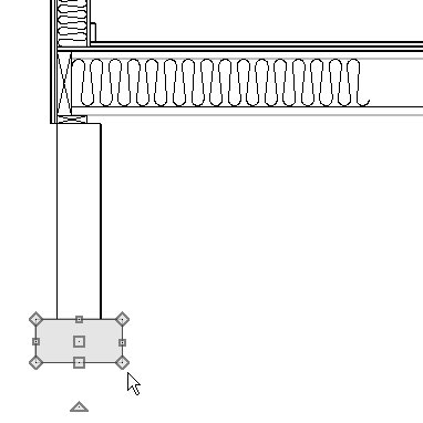
- Like Insulation Boxes, Rectangular Polylines will snap to objects and surfaces in the view.
- In this example, a Rectangular Polyline is drawn over the stem wall footing.
- Like Insulation Boxes, Rectangular Polylines will snap to objects and surfaces in the view.
- Click on the polyline to select it, then click the Open Object
 edit button. On the Fill Style panel of the Polyline Specification dialog:
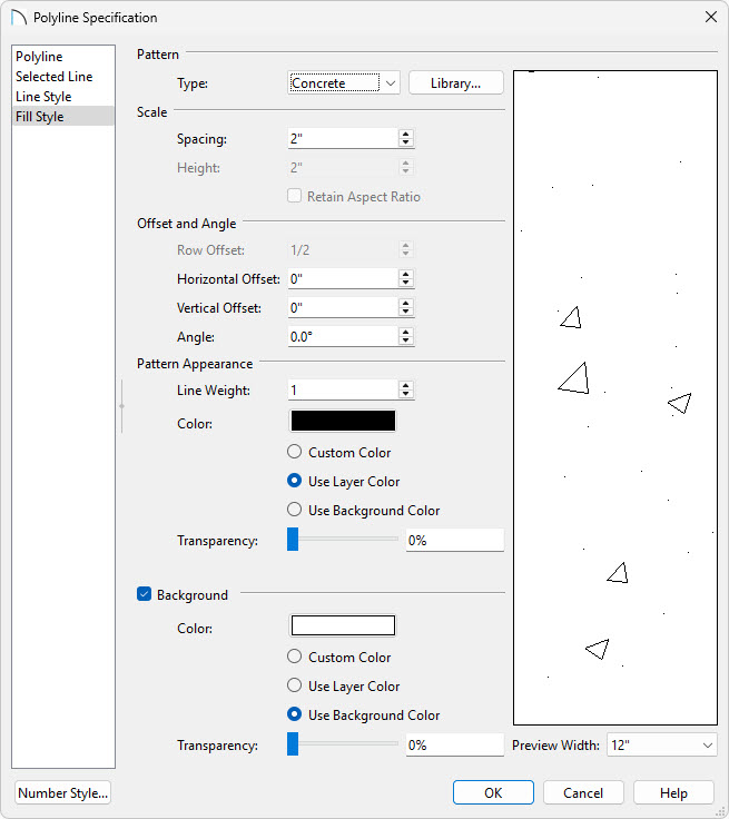
- Select "Concrete" from the Type drop-down list.
- Adjust the Scale, Offset and Angle, and Pattern Appearance settings to your liking.
- Click OK.
- Select "Concrete" from the Type drop-down list.
- Add a second polyline, as described above, for the stem wall.
- Draw another rectangular polyline outside of the stem wall using the details described in Step 3, above, and assign this polyline a Weave fill style.
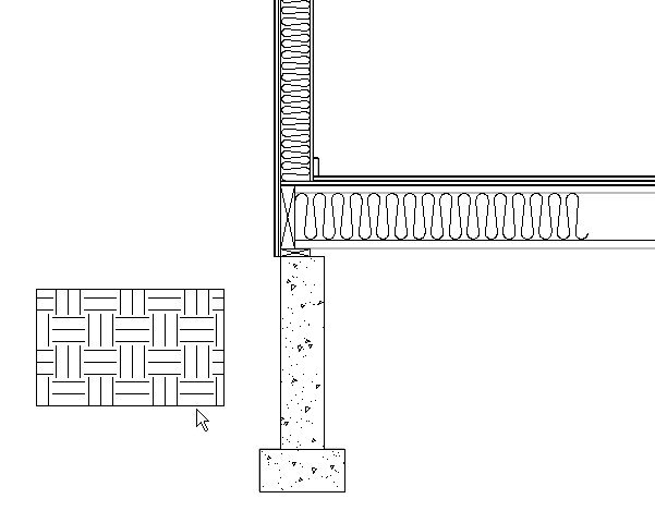
- Click on the polyline to select it.
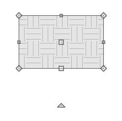
- Click the Add Break
 edit button.
- Click along one of the polyline's edges.
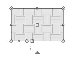
- A new corner edit handle is created at that location.
- Click and drag that new corner handle to reshape the polyline.
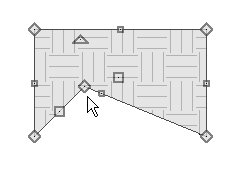
- Click the Add Break
- Polyline edges can also be curved. Click on one of the polyline's edges to select it.
- When an edge is selected, the square edit handle located along its length will be larger than the square handle on the other edges.
- With an edge selected, click the Change Line/Arc
 edit button.
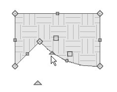
- The selected edge is converted from a straight line into an arc.
- Click and drag the small triangular Reshape edit handle to change the arc's length, or click the small circular Resize handle to change its radius.
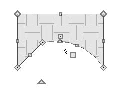
- Click the Change Line/Arc
 button once more to convert it from an arc into a straight line.
- When an edge is selected, the square edit handle located along its length will be larger than the square handle on the other edges.
- Adjust the polyline as needed to create the desired shape.
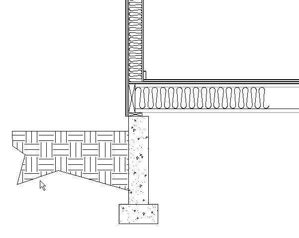
Detail drawings rarely show the entire structure. Instead, lengthy components like walls and floor platforms are truncated using a break line. If you were to draw your cross section detail by hand using the CAD tools alone, you could create a break line using a simple open polyline. Because details in Home Designer are added to a cross section of the entire structure, it may be helpful to create a closed polyline with a solid white fill to hide unneeded portions of your cross section.
To add break lines
- Select CAD> Boxes> Rectangular Polyline
 from the menu, then click and drag to draw a rectangle
- Click on the rectangle to select its top or bottom edge, then click on the temporary dimension that displays its height.
- In the inline text field, type the desired height of the polyline.
Note: If you do not see Temporary Dimensions, select View> Temporary Dimensions from the menu to toggle them on.
- In this example, the height is specified as 18".
- In the inline text field, type the desired height of the polyline.
- With the polyline still selected, use the Add Break
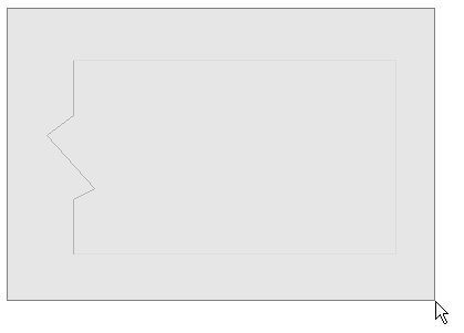
 edit tool to add four new edit handles to one of its vertical edges, as shown in the image below.
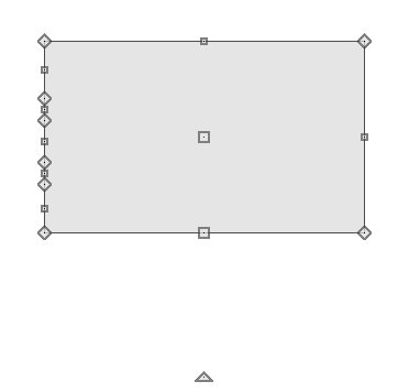
To space the breaks evenly, draw CAD lines through the polyline and position them at regular intervals using dimension lines. Then, use Object Snaps to add corner edit handles at the points where the lines intersect the polyline.
- Click and drag the two corner handles closest to the polyline edge's center point to produce a zig-zag shape.
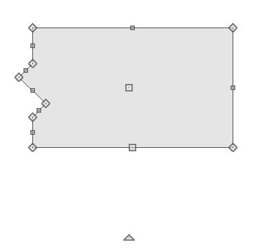
- With the polyline selected, click the Open Object
 edit button and in the Polyline Specification dialog:
- On the Line Style panel, specify a light grey line color.
- On the Fill Style panel, specify a Solid fill pattern that is white in color.
- Click OK to close the dialog and apply your changes.
- On the Line Style panel, specify a light grey line color.
- With the polyline still selected, click the Copy/Paste
 edit button, then the Paste Hold Position
  secondary edit button.
- This will create an exact copy of the break line polyline located directly on top of the original.
- As soon as it is created, this newly created copy will be selected.
- This will create an exact copy of the break line polyline located directly on top of the original.
- With the newly copied polyline selected, click the Open Object
 edit button, and on the Line Style panel of the Polyline Specification dialog, specify the default black line color.
- Click the Select Objects
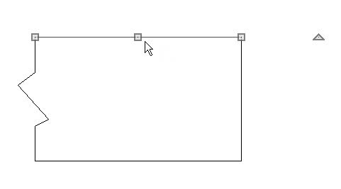
 button, then click the topmost edge of the copied polyline.
- Click the Disconnect Selected Edge
 edit tool.
-
Click the Delete
 edit tool or press the Delete key on your keyboard.
-
Repeat this process for the rightmost and bottom edges of the copied polyline.
- Click the Disconnect Selected Edge
- Select the closed polyline with the light grey line color and change its line color to white.
- Click the Select Objects
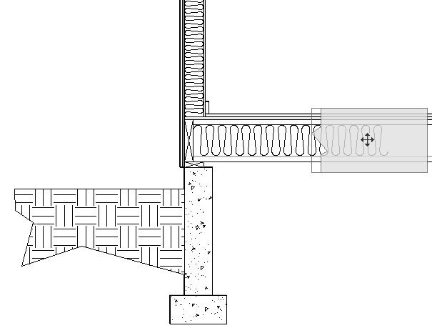
 button, then click and drag a rectangular selection marquee around the two polylines.
- Use the Move
 edit handle to position the break line polylines as needed in the drawing.
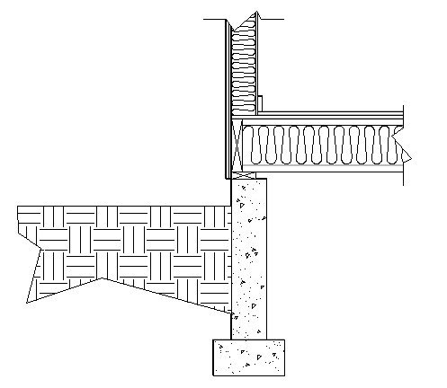
- Use the Copy/Paste
 edit tool to make copies of the two polylines if your detail drawing requires more than one break line.
To add text
- Select Edit> Default Settings
 from the menu, and in the Default Settings dialog:
- Expand the list for Text, Callouts and Markers
- Click on Rich Text and then click on the Edit button.
- Expand the list for Text, Callouts and Markers
- On the Rich Text panel of the Rich Text Defaults dialog:
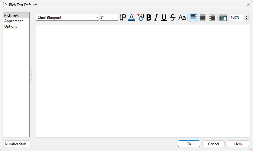
- Specify the desired Font.
- Specify the Size of text you'd like to use. In this example 2" is used.
- Specify the Color of text.
- Make sure that Align Left
 is selected.
- To learn about the various other options seen here, click the Help button to open the program's Help documentation.
- Specify the desired Font.
- On the Options panel, check the box beside CAD Stops Move and then click OK.
- Click on Arrow in the Default Settings and click the Edit button to open the Arrow Defaults dialog.
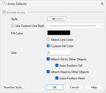
- Specify the Style you'd like your arrows to use.
- Specify the Fill Color of the arrow.
- Adjust the Size to your liking. In this example 3" is used.
- To learn about the various other options seen here, click the Help button to open the program's Help documentation.
- Specify the Style you'd like your arrows to use.
- Click OK to close the Arrow Defaults and then click Done.
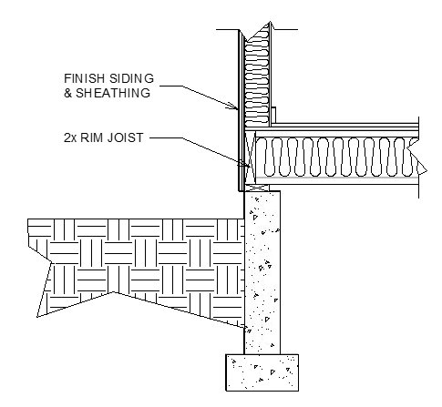
- Select CAD> Text> Text with Arrow
 from the menu, then click once in the drawing area to the left of the cross section detail to open the Rich Text Specification dialog.
- Type the desired information in the Text field and click OK.
- A text object with a line with arrow attached is created at the location where you clicked.
- Type the desired information in the Text field and click OK.
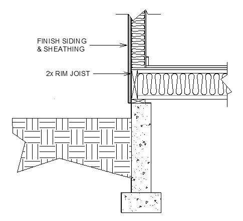
- Click on the line with arrow to select it, then use its edit handles to point it at the object its text describes in the cross section detail.
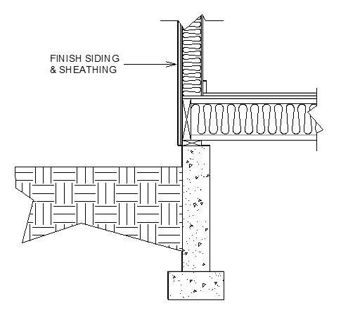
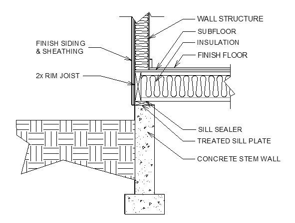
- Repeat these steps to create additional text objects, as needed.
To align text objects
- Select CAD> Lines> Draw Line
 from the menu, then click and drag to draw a vertical line through the entire height of the area where you have added fill and other details.
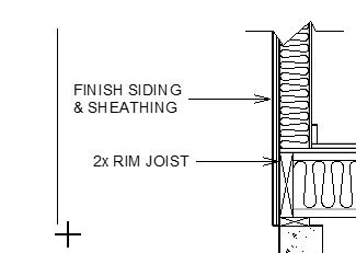
- Click on the line to select it, then move it away from your detail the distance that you would like your text to be. This line will serve as a temporary ledger to align your text to.
- Click the Select Objects
 button, then click on a Rich Text object to select it. Using its Move
  edit handle, drag it towards the CAD line you just drew until it bumps into it.
- Repeat this process to bump all of your Rich Text objects into the CAD line. Notice that the line with arrow attached to the text adjusts its length to meet the CAD line, as well.
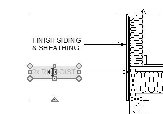
- To add corners to the lines with arrows that are aligned with one another, draw a second line where you would like the breaks.
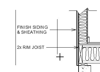
- Select a line with arrow and click the Add Break
 edit button.
- Click on the line with arrow where it crosses the CAD ledger line you just drew.
- When Object Snaps
 are enabled, a red snap indicator will display when your pointer is over the intersection.
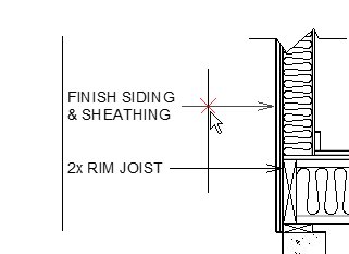
- Click once to create a new corner at that location.
- With the line with arrow still selected, edit its shape as needed.
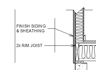
- Click on the line with arrow where it crosses the CAD ledger line you just drew.
- Repeat this process to edit all lines with arrows that intersect your ledger line.
- When you are finished, you can select the CAD lines and click the Delete
 edit button or press the Delete key on your keyboard.
Cross section details often have text on both the left and right sides of the detail. You can repeat the steps above to create text on the right side, as well. To make a Rich Text object right-justified, select it and click the Align Right  edit button.
To send the detail to layout
- When your cross section detail is complete, select select 3D> Save Active Camera
 and then File> Save
  to save your work.
- Select File> Send to Layout
 to open the Send to Layout dialog.
When using Project Management in Home Designer 2026 and newer, the view will be sent to the layout that is inside of your project. If a layout hasn't been created yet, this will create a new layout within your project.
When using Traditional File Management in Home Designer 2026 and newer, or when working with Home Designer Pro 2025 and prior, the view will be sent to the layout file you have open. If you do not have a layout file open it will create a new layout file.
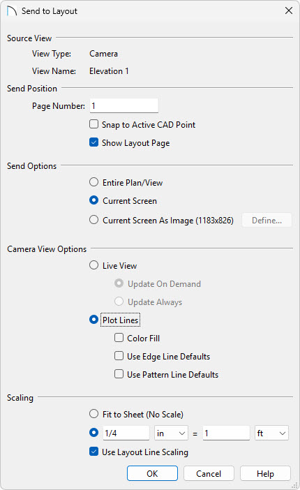
- Make sure Current Screen is selected.
- Select the Plot Lines radio button.
- Check the Color Fill box if you'd like your detail to be in color.
- In the Scaling section, specify the scale you'd like to display the CAD Detail at on your layout sheet.
- Click OK.
- Make sure Current Screen is selected.
- Depending on the selected scale, a message may warn you that the view is too large to fit on the layout sheet. Click OK. This may be alright, because in a moment the view box will be resized smaller to show only the detail that you created.
When you send the view to layout, it may show content that you don't want to be visible. This can be resolved by cropping the layout box.
To crop the view on the layout page
- If the layout page is not currently active, select the tab associated with the layout file.
- If you cannot see the entire cross section view in layout, select Window> Fill Window
 from the menu.
- Click the Select Objects
 button, then click on the cross section view to select it.
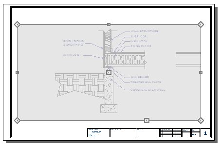
- Using its edit handles, reduce the size of the layout view box until it only shows the details you want to see.
