Creating a Reverse Sloped Driveway
Pro | Architectural | Suite
QUESTION
I have modeled my terrain, and now need to cut in to it to create a driveway with retaining walls. How can I model this in Home Designer?

ANSWER
Creating a reverse sloped driveway is easy to accomplish using the Terrain tools in the software.
This article assumes that the reader is familiar with and comfortable using terrain elevation lines, modifiers and editing custom shaped features. If you are not yet familiar with using these terrain tools, please review the online tutorial training videos on terrain that are applicable to your version, as well as the information provided in the Related Articles section below.
To create a retaining wall
- Before you can add a retaining wall to your plan, you first must have a terrain perimeter present. With Floor 1 active, select Terrain> Create Terrain Perimeter
 to add a completely flat terrain.
Note: If Create Terrain Perimeter is grayed out and inactive, it means that you already have a terrain perimeter in the plan or are in an unsupported view. Ensure that you're in a plan view, then check both Floor 0 and Floor 1 to attempt to locate an existing terrain perimeter.
- Once the terrain perimeter has been added to your plan, you can use the Elevation Data
 and Terrain Modifier
  tools to create terrain that slopes in a wide variety of ways to best model the terrain of your lot.
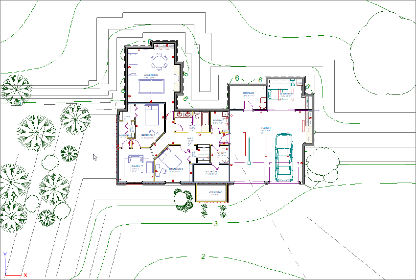
For the purposes of this example, a number of elevation lines have been added to the terrain surrounding the house, but none in front of the area that will become the driveway, as that terrain data will be added later.
You may find it helpful to create a Full Overview of the plan and use the Window> Tile Vertically option so that you can see how the changes you make in the 2D floor plan view affect the 3D camera view of the Terrain.

- Next, select Terrain> Terrain Wall and Curb> Straight Retaining Wall
 , then click and drag to create retaining walls out from the garage.
Note: A retaining wall's height is determined by the elevation of the terrain on each side. By default, the height of the wall matches the terrain on the high side of the break, and the bottom matches the low side. If you insert a retaining wall in to flat terrain, it will look like a concrete strip in 3D camera views.
Home Designer Pro has the ability to create stepped retaining walls by adding breaks and modifying the shape in camera views.
Once the retaining walls have been added, you are ready to adjust the terrain inside of them to create a reversed slope from that of the rest of the terrain.
To create a sloped driveway
-
Select Terrain> Elevation Data> Elevation Region
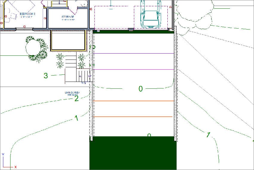
 , then click and drag to create a rectangular region in front of the garage approximately 12" wide.
-
Using the Select Objects
 tool, click on the newly created region, then click on the Open Object
  button to display the Elevation Region Specification dialog.
-
On the Elevation panel, type in an Elevation value so that the front of the sloped driveway will be at the same level as the garage doors, then click OK.
For the purposes of this example, we used a value of -9 1/2".
- Repeat this process to add an elevation region at the top of the driveway, with an appropriate height for where the driveway will meet the road.
For the purposes of this example, we used a value of 0".
-
Next, in the area between the the retaining walls and elevation regions, select Terrain> Elevation Data> Elevation Line
 , then click and drag out several elevation lines.
-
Select one of the elevation lines and click on the Open Object
 edit tool to display the Elevation Line Specification dialog.
-
On the Elevation panel, set the Elevation for each one of the lines so that they indicate the terrain will be lower near the garage doors, and higher until they reach the elevation region at the end of the driveway.
For clarity in the example below, we have set the Fill Style for the two elevation regions to a dark green. The purple elevation line is set to -4", the pink elevation line is set to -2", and both orange elevation lines are set to 0".

-
To create a driveway in this space, which will follow the sloped terrain, select Terrain> Road and Sidewalk> Driveway Area
 , then click and drag out a rectangular polyline representing the driveway, and open its Specification dialog to set the Terrain to Top, Thickness, and the Materials of the driveway surface.
For the purposes of this example, a Terrain to Top value of 2" and a Thickness of 6" are specified.
You can also apply a Fill Style with a Transparent Pattern Background to more easily be able to select and edit the driveway surface. Driveways can be reshaped using the Break Line and Change Line/Arc edit tools and resized using their edit handles.
-
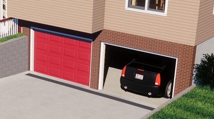
Customizing the driveway, such as to model a trench grate for drainage, can be created by selecting Terrain> Feature> Rectangular Feature
 and applying an appropriate material to it.
For the purposes of this example, we will use the Decorative Perforated Metal Panel from the Materials Wire and Lattice Bonus catalog.
