Stepping Terrain for a Terraced Flower Bed
Pro | Architectural | Suite
QUESTION
I want to create a stepped, terrace style of garden or planting bed. How do I do that?

ANSWER
Using Elevation Regions, Retaining Walls, and Garden Beds, you can model a stepped garden bed, then place plant images to customize its appearance.
For the purposes of this example, we will walk through creating a basic stepped, or terrace style, flower bed.
To create different elevated regions
-
If your plan does not already have a Terrain Perimeter, select Terrain> Create Terrain Perimeter
 to create one and resize it as needed.
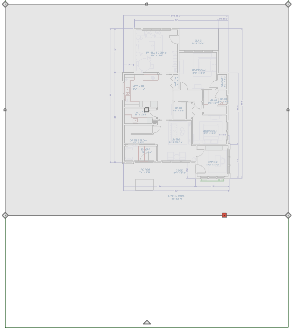
- If your plan already has a structure in it, select Terrain> Elevation Data> Elevation Region
 and draw a rectangular flat region within the Terrain Perimeter around the house, similar to the image shown below.
- Once placed, use the Select Objects
 tool to select the Flat Region and choose Open Object
  to display the Flat Region Specification dialog.
- On the Elevation panel, verify that the Elevation is set to 0" and click OK to close the dialog.
- Repeat this process to create several additional Flat Regions which will become the steps in the garden terrace.
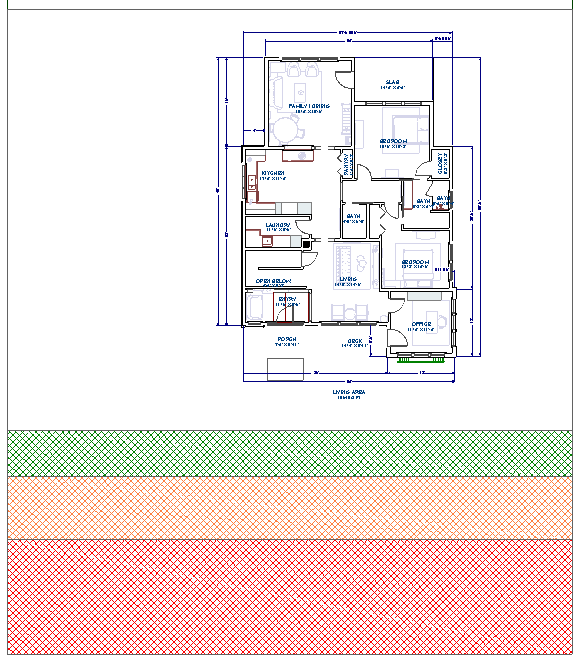
You may find it easier to work with elevation regions by selecting the Fill Style panel and choosing a Fill Pattern and Fill Color to help differentiate between the various regions in plan view.
-
Set the Elevation of the second Flat Region, represented above in a green angle grid pattern, to -24" (or -2').
-
Set the Elevation of the third Flat Region, represented above in a orange angle grid pattern, to -48"(or -4').
- Set the Elevation of the fourth Flat Region, represented above in a red angle grid pattern, to -72" (or -6').
-
Set the Elevation of the second Flat Region, represented above in a green angle grid pattern, to -24" (or -2').
To create retaining walls
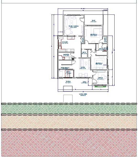
- Next, select Terrain> Terrain Wall and Curb> Straight Retaining Wall
 , and click and drag out Retaining Walls in between each of the Flat Regions.
You may want to place a Straight Curb partway through the lowest Flat region to signify the end of the planting bed in that area.
- By default, the Retaining Walls will have a concrete material applied to them. To change this, use the Select Objects tool to select one of the Retaining Walls and choose Open Object to display its specification dialog.
- Go to the Materials panel, select Exterior Wall Surface component, then click the Select Material button.
- Locate and choose the desired material for the wall, then click OK.
- Follow the same procedure to change the Interior Wall Surface.
- Once both wall surfaces have the appropriate material applied to them, click OK to apply the material change and close the specification dialog.
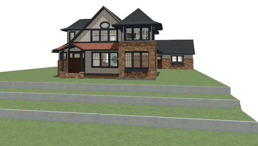
- Follow the same procedure to change the remaining Retaining Walls, then take a Perspective Full Overview
 to see the results so far.
- Close the 3D view and return to the 2D floor plan view.
Now, you are ready to place garden beds.
To create garden beds
-
Select Terrain> Garden Bed> Polyline Garden Bed
 and place a rectangular garden bed across the Flat Regions.
The Garden Bed will follow the terrain each time it lowers, so it is not necessary to place individual beds for each Flat Region, unless you want to apply a different material to each one.
Both terrain regions and gardens beds can be edited in shape and size after they are placed, much like the Terrain Perimeter, using the Change Line/Arc and Add Break edit tools.
-
Once placed, use the Select Objects tool to select the Garden Bed, and click the Open Object edit button to display the Garden Bed Specification dialog.
-
Go to the Materials panel, select the second Terrain Garden Feature component, then click the Select Material button.
-
Locate and choose the desired material for the Garden Bed, then click OK.
In this example, the Mulch - Dark material is used, which is the default. Similar materials can be found by navigating to Materials. Landscaping and Roadways.
- Click OK again to confirm the changes and close the dialog.
-
Now you are ready to add plants to your design using either the Library Browser
 or Plant Chooser
  .
.