Creating a Suspended Ceiling
Pro
QUESTION
How do I show a suspended ceiling with recessed lights that fit the ceiling tile grid?

ANSWER
A suspended ceiling can be created in Home Designer 2026 and newer, or legacy Home Designer Pro versions, by setting your ceiling finish, using the ceiling tile material, and placing lighting.
To configure the suspended ceiling
- Go to Build> Wall> Straight Exterior Wall
 and click and drag to create walls to form your structure.
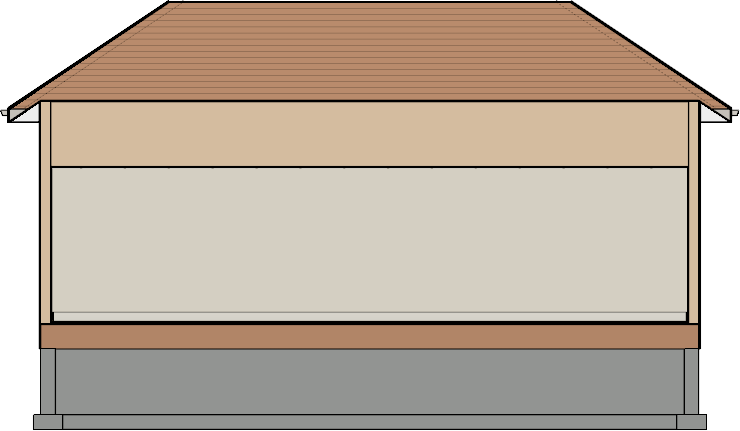
In this example, a simple 30' x 50' structure is created.
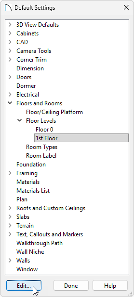
- Click Edit> Default Settings
 , expand Floors and Rooms, expand Floor Levels, select the 1st Floor option, then click Edit.
Setting the defaults will affect all rooms on your 1st floor. If only some of your rooms will have a suspended ceiling you will want to do the following steps in the Room Specification instead.
- In the 1st Floor Defaults dialog, on the Structure panel, specify your Ceiling height.
In this example, 121 1/8" is used.
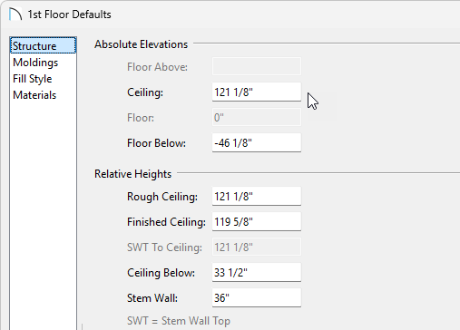
- Remaining on the Structure panel, click Edit next to your Ceiling Finish to define the ceiling finish.
- In the Ceiling Finish dialog:
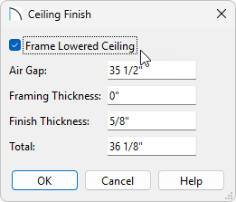
- Check the box for Frame Lowered Ceiling.
- Set the thickness of your Air Gap.
In this example, 35 1/2" is used.
- Specify your Framing Thickness. If you will have no framing directly above the ceiling tiles, set this to 0".
In this example, 0" is used.
- Set the thickness of your Finish Thickness.
- Click OK when you're done with your changes.
- Check the box for Frame Lowered Ceiling.
- On the Materials panel, select the Ceiling Finish component, then click Select Material.
- In the Select Material dialog, go to Core Catalogs> Materials> Ceiling Tiles> False Ceiling, select one of the ceiling tile materials, and click OK.
In this example, the Square Ceiling Tile material is used.
- Make any other desired material changes and click OK.
- Click Done to close out of your Default Settings.
Now we will have the ceiling tile material, but it will likely not align perfectly to the corner. We will need to adjust the material to properly align from the corner.
To orientate the ceiling tile material
- Create a wall elevation of a perimeter wall by going to 3D> Create Orthographic View> Cross Section/Elevation
 and clicking and dragging inside of your structure towards the shorter 30' wall.
- Using the Select Objects
 tool, click on the wall, then click on the Open Object
  edit tool.
- In the Wall Specification, on the Materials panel, select your Interior Wall Surface and click Select Material to open the Select Material dialog.
- In the Select Material dialog navigate to Core Catalogs> Materials> Ceiling Tiles> False Ceiling, select the same ceiling tile you used for your ceiling, and click OK.
In this example, Square Ceiling Tile is used.
- Click OK to close the Wall Specification.
- Remaining in your cross section, go to CAD> Dimensions> Tape Measure
 , and then measure the distance from the grid to your wall.
In this example, the X value is offset by 1' 7" and the Y value is offset by 1' 1/2". These are the values we will use to offset your material.
It may be helpful to disable Grid Snaps to get an accurate measurement. These can be disabled by going to Edit> Snap Settings> Grid Snaps. Once you're done taking your measurements, ensure you turn these back on by going to Edit> Snap Settings> Grid Snaps.
- To adjust the ceiling tile material, go to 3D> Adjust Materials> Adjust Material Definition
 , and click on the ceiling tile material on your wall to open the Define Material dialog.
- In the Define Material dialog:
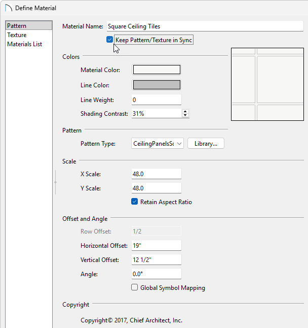
- On the Pattern panel, ensure that Keep Pattern/Texture in Sync box is checked.
- Adjust the Horizontal Offset to the value measured above in Step 6.
- Adjust the Vertical Offset to the value measured above in Step 6.
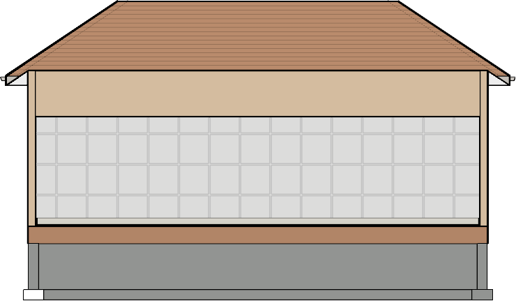
- Click OK to save your changes, and the ceiling tile should now accurately align with the edge of your wall.
- On the Pattern panel, ensure that Keep Pattern/Texture in Sync box is checked.
- Using the Select Objects tool, click on the wall, then click the Open Object edit tool.
- In the Wall Specification, on the Materials panel, select your Interior Wall Surface and click Select Material.
- In the Select Material dialog, check the box for Use Default Material towards the bottom, click OK and OK again to close the dialogs.
To place lights
- Close the 3D view to return to your floor plan view.
- Click View> Library Browser
 and within the library browser, select the desired lighting fixture. Place the desired number of lights into the plan.
In this example, the Core Catalogs> Architectural> Lighting> Tube Lighting> Recessed> 24" x 24" LED Recessed Tube Light is used.
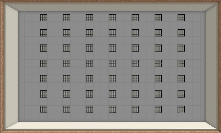
- Next click 3D> Create Camera View> Perspective Full Overview
 and using the Mouse-Orbit Camera
  feature rotate the view until a straight on view of the bottom of the structure is seen.
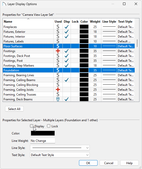
- From the menu, click on Tools> Display Options
 .
.
- In the Display Options dialog, uncheck the Disp column for the "Foundation" and "Floor Surfaces" layers, then click OK.
If the area is already furnished you may need to uncheck the Furniture and Fixtures layers as well.
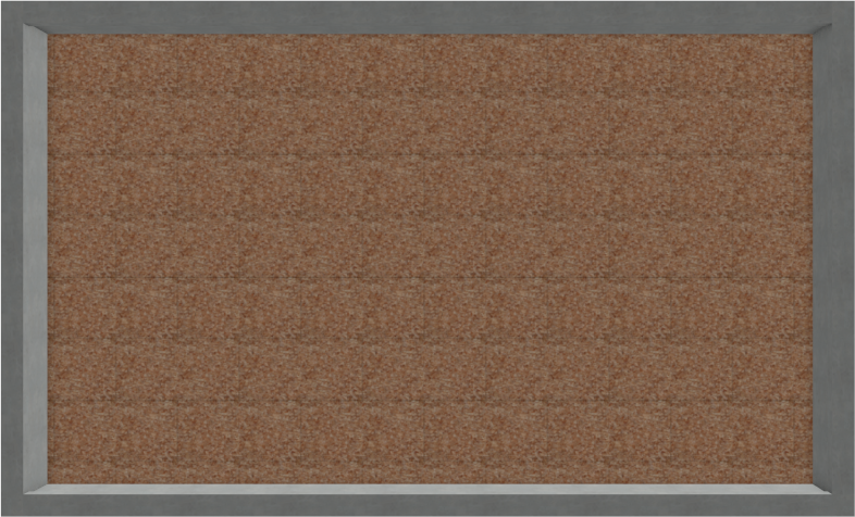
- Now it is possible to view the ceiling surface and the light fixtures. Select one of the light Fixtures and place it within the grid provided by the Ceiling Tiles material.
If you have trouble getting the light within the grid, hold down the Ctrl/Command key on your keyboard to allow for free movement.
You may find it helpful to disable the Temporary Dimensions, which can be enabled/disabled by going to View> Temporary Dimensions.
To quickly create a lighting grid, you can utilize the Transform/Replicate edit tool to create copies of your lights.
- When lights are placed, click Tools> Display Options and put a check the Disp column to display the "Foundation" and "Floor Surfaces" layers that we previously disabled in Step 5.
- Close the 3D view to return to your floor plan view.
- Click 3D> Create Camera View> Full Camera
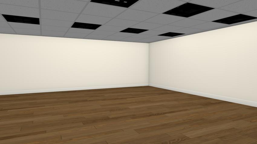
 then click and drag a camera view to see the results.