Customizing Stair Landings
Pro | Architectural | Suite
QUESTION
I have a set of stairs which start or meet at an odd angled landing. How can I model this in Home Designer?

ANSWER
You can draw a variety of stair sections joined by a landing, including T-shaped staircases, U-shaped staircases, as well as many more unconventional styles using the stair tools within your Home Designer Software.
If you only have two stair sections that need to be connected, you can easily create the stair landing between them with a single click.
Editing a Stair Landing in Home Designer software is much like editing other closed polyline-based objects such as Custom Countertops, Terrain Features, etc.
There are a few things to keep in mind when drawing stairs:
- Before stairs are created, make sure that the heights for both the lower and upper floors are correctly defined.
- Stairs are drawn going UP, so they should be drawn from the lower of the two floors they connect.
- Stairs adjust their riser and tread dimensions to connect two floor heights if possible. The rise and run are calculated so that the steps are consistent in size.
- If you have the Reference Display
 turned on, stairs snap to the reference display.
- If a stairwell room has been defined on the floor above, the top of the stairs can be dragged until it stops at the railing or wall defining the stairwell.
To create a stair landing automatically
- First, launch Home Designer and Open
 the plan in which you would like to create your irregularly shaped landing.
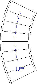
- Select Build> Stairs> Draw Stairs
 , then click and drag to create your first stair section, starting at the bottom and drawing upward.

- Using the Select Objects
 edit tool, select the straight stair section, then click on the Change Line/Arc
  edit tool to make this section curved.
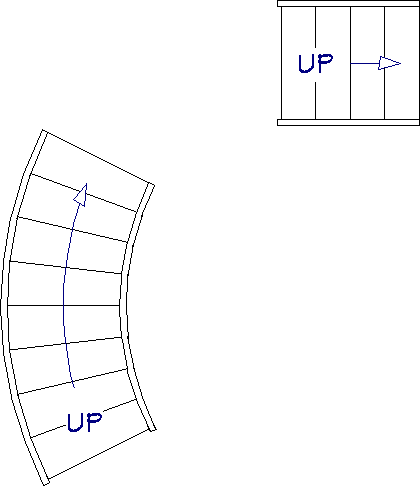
- Next, draw in your second section of stairs in the same manner, approximately where they should be in relation to the first set of stairs.
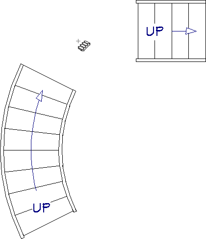
- With the Draw Stairs tool still active, click in between the two stair sections.
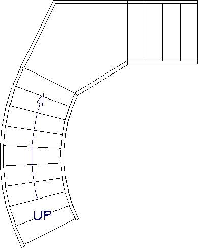
- You can see that instead of a standard rectangular landing, the two stairs are connected with the appropriate landing shape and size.
Once you have a landing placed in your plan, it is easy to edit it into almost any shape by selecting it and using the Change Line/Arc  and Break Line
  edit tools. Below is an image with some of the edit handles you may want to familiarize yourself with before editing stair landings.
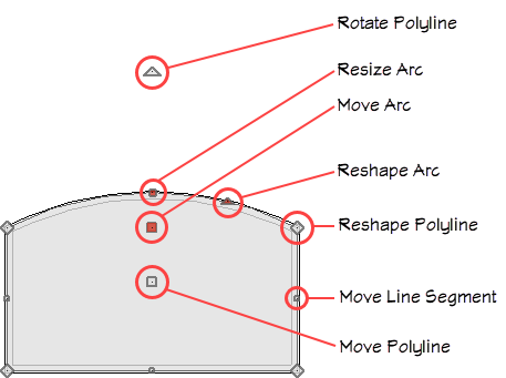
If you are unfamiliar with the functions of these edit handles within your software, select the Help menu and click on Launch Help to display the software's searchable help menu.
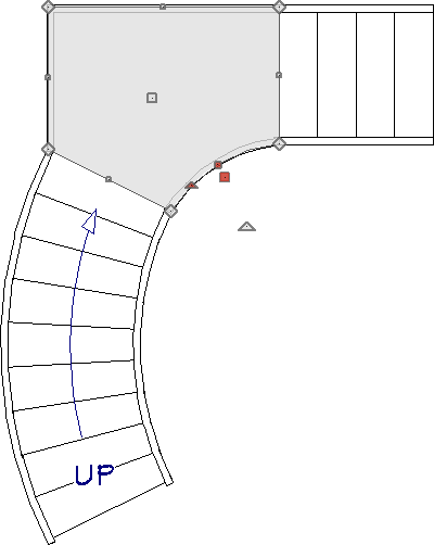
To edit the shape and size of a stair landing
- To change one of the segments of the landing into an arc, choose the Select Objects
 tool, and click on the edge of the landing that you want to change.
- Select the Change Line/Arc edit tool.
- You can also use the Change Line/Arc edit tool on straight stair sections to change them into curved stair sections.
- Note that only the edge that you selected will change. You will need to select each edge you want to turn into an arc and use its edit handles to reshape it appropriately for your particular custom landing shape.
- You can also use the Change Line/Arc
- The Break Line edit button can be used to create a new corner edit handle at the location of the break.
- Break points are also referred to as joints, nodes or pivot points.
If you happen to place more breaks than are necessary for your stair landing, you can easily remove them by selecting the diamond edit handle at the break and dragging it over to the next diamond edit handle. Alternatively, you can select the Simplify Polyline edit tool when a landing is selected to remove unused break points.
- Another reason to place a break would be if you needed to have two stair sections connected to the same edge of a landing, and have received the following error message: "Only one stair section can connect to a single landing edge. Select the landing and use the Break Line edit button to break the landing edge so each stair section has its own landing edge to connect to."
To resolve this warning, select the Break Line edit tool and click at the location on the landing in between where the two stair sections will be before placing the second stair section, as demonstrated in the image below.
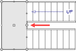
Notice that you do not need to move this edge of the landing, simply placing a break at the correct location creates the necessary extra edge to which the stair section can attach.
- Break points are also referred to as joints, nodes or pivot points.
- Continue modifying the stair landing until it is the desired size/shape.
To create an independent stair landing
- Select Build> Stairs> Landing
 , then click and drag out a basic rectangular landing.
- Use the methods described earlier in this article to customize its size, shape, and position.
- Once the landing is to your liking, use the Select Objects tool to select it, then click on the Open Object
 edit tool.
- On the General panel of the Stair Landing Specification dialog that displays, you can modify the thickness and height of the landing, as well as whether or not you want railings to generate on each edge.
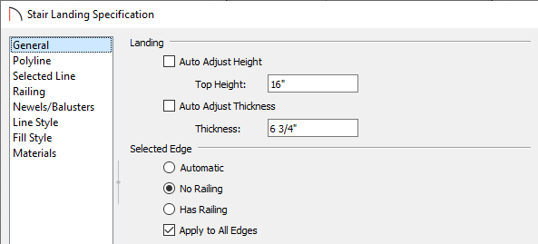
- Uncheck Auto Adjust Height When Connected to Stairs and set the desired Top Height value.
- Uncheck Auto Adjust Thickness When Connected to Stairs and set the desired Thickness value.
- Select the appropriate railing options under the Selected Edge section.
- Select Automatic to suppress the railing on any portion of the selected edge that either connects to a stair section or has an adjacent landing, but to produce a railing where that is not the case.
- Select No Railing to suppress the railing on the selected edge of this landing.
- Select Has Railing to produce a railing along the selected edge, even where it connects to a stair section or has an adjacent landing.
- Check Apply to All Edges to apply your selection to all edges of the landing. This is an action rather than a state - the next time this dialog is opened, this box will be unchecked.
When you click on a polyline- or box-based object, the edge that you click nearest becomes the "selected edge" and displays an edit handle larger than those on other edges. The handle on this edge may also display at the point where you clicked to select it.
- Select Automatic to suppress the railing on any portion of the selected edge that either connects to a stair section or has an adjacent landing, but to produce a railing where that is not the case.
- Uncheck Auto Adjust Height When Connected to Stairs and set the desired Top Height value.
-
If railings are specified for the landing, you can adjust the railings properties on the Railing and Newels/Balusters panels of the Stair Specification dialog.
-
Once all desired changes have been made to the landing, click OK to close the dialog.
- You can add additional landings at the top or bottom of stair sections, or even up against other landings, and the heights will adjust automatically.
Note: Multiple landings can be used to create custom situations that may not be possible with the other Stair tools. For example, if you want to simulate multiple stair treads that all have a different width or height, you can use independent landings, and adjust their properties individually.