Increasing the Field of View for a 3D Camera View
Pro | Architectural | Suite
QUESTION
I would like to increase the Field of View when I take a camera view so that more of my image is included. How can I accomplish this?
ANSWER
The Field of View refers to a camera’s field of vision. A wider field of view makes the focal point appear further away, as more of the image is included in the same view window.
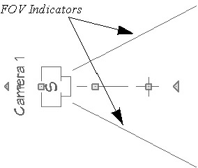
In plan view, the angled lines of a camera symbol indicate its field of view, and a camera’s field of view can be adjusted in the Camera Specification dialog.
To create the view
- Select 3D> Create Camera View> Full Camera
 , then click and drag out your camera view.
- Select Window> Tile Vertically
 so that you can see how the adjustments that you make affect both the 2D floor plan view, and your 3D camera view.
To use the Camera Specification dialog to adjust the view
- While in the camera view, select 3D> Edit Active Camera
 .
.
- In the Floor Plan view you can use the Select Objects
 tool to click on the camera, then click on the Open Object
  edit button to display the same dialog.
- In the Floor Plan view you can use the Select Objects
-
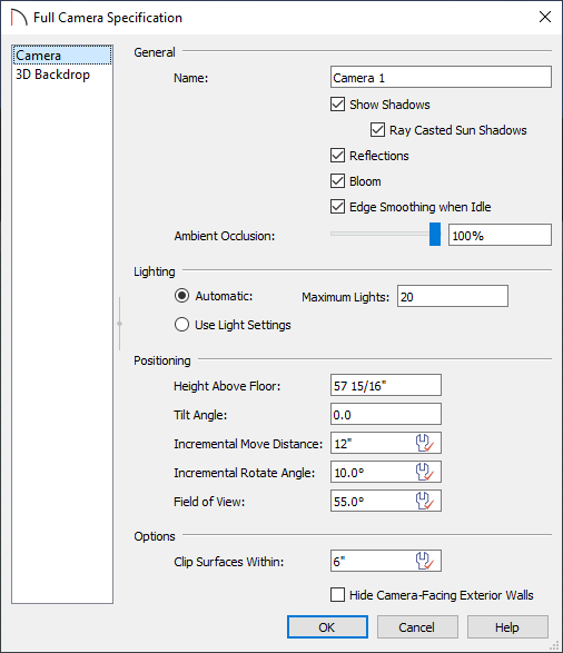
On the Camera panel of the Camera Specification dialog that display, focus on the Positioning section.
-
Height Above Floor defines the height that the camera is above the floor level for the current floor.
-
Tilt Angle determines the vertical angle the camera is tilted. The camera maintains its focal point and position in plan view, but if the camera is tilted, the focal point is above or below the current camera height.
-
Incremental Move Distance controls how far the camera moves each time you Pan in any direction or Dolly forwards or backward using the keyboard, toolbar buttons, or menu. For interior views a small number is good, but for exterior you may want a larger increment.
-
Incremental Rotate Angle defines how many degrees the camera rotates each time you Tilt, Orbit, or Dolly side to side using the keyboard, toolbar buttons, or menu. A setting of 90° would make one full rotation in four moves.
- Field of View defines the camera’s field of vision in angular degrees.
Note: Depending on the type of camera view selected, not all the settings in the Camera Specification dialog may be editable. In addition, some settings only affect some types of views.
-
Height Above Floor defines the height that the camera is above the floor level for the current floor.
- When you have finished making adjustments in this dialog, click OK to apply them and close the dialog.
Pay attention to how your 3D camera view updates, as well as how the symbol in floor plan view updates to reflect the changes that you have made.
To modify the camera in plan view
While still in your 2D floor plan view, use the Select Objects tool to click on the camera.
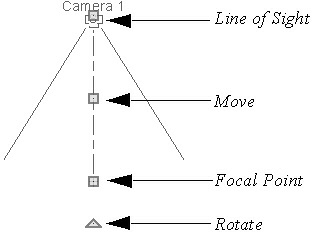
- Drag the Line of Sight handle to change the camera angle without moving the focal point.
- Drag the Move handle to relocate the camera while maintaining its relative angle.
- Drag the Focal Point handle to reposition the focal point and change the line of sight without moving the camera.
- Drag the Rotate handle to rotate the camera’s line of sight about its center.
The 3D view corresponding to the camera symbol reflects changes made to the symbol in floor plan view.
Multiple camera symbols can also be selected; however, their editing options are limited to being moved, rotated, and deleted.