Creating a Custom Staircase Using Landings
QUESTION
I need to create an unorthodox staircase that consists of multiple treads with unique properties. Is there a way to accomplish this?

ANSWER
A staircase consisting of custom stair treads can easily be created using multiple landing objects, all of which can be placed using the Landing tool. Although the Landing tool is typically thought of when creating a platform between multiple stair sections or to another floor platform, its versatility allows it to be used to create individual stair treads.
One benefit of using landings is that they will recognize stairs, as well as other individually placed landings, and will automatically adjust their height when connected to these like components. Additionally, you're also able to disable this automatic functionality and input your needed specifications for finer control, which is the method we'll be covering in this article.
Another benefit is that landings can be customized using the polyline edit tools to be any shape you desire, giving you the ability to create a fully custom staircase consisting of different sized treads.
In this example, we will be creating custom starter treads, each at a different size, which can only be accomplished using the Landing tool.
To create a custom staircase using landings
- In the file you'd like to create the custom staircase in, select Build> Stairs> Landing
 and click and drag to create a landing that we will shape into your your custom tread.
Alternatively, with the Landing tool active, you can click to place a landing.
- Use Temporary Dimensions
 or the various edit handles to resize the landing.
Temporary Dimensions can be toggled on/off by going to View> Temporary Dimensions.
- Select the landing and use the Open Object
 edit tool to open the Stair Landing Specification. On the General panel of the Stair Landing Specification:
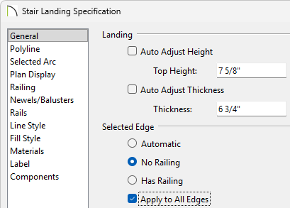
- Uncheck the box for Auto Adjust Height.
Note: A free-standing interior landing will have a default Top Height equal to one riser plus the thickness of the default floor finish. A free-standing exterior landing will have a default top height equal to its thickness. When this box is checked, the landing height may adjust as needed to maintain consistent riser height in all connected stair sections, ramp sections, or adjacent landings.
If snapping the edges of your landings together you can keep the Auto Adjust Height box selected, as it will automatically raise your landings to create steps. In this example we will not be snapping the landings together, so we will turn off the automatic functionality.
- Uncheck Auto Adjust Thickness and set the Thickness to however thick your tread will be.
In this example, we will use 6 3/4".
Note: A free-standing landing will have a default thickness of 6 3/4” (169 mm). When checked, the thickness is based on the riser height of the stair sections it is attached to, or the thickness of the ramps it is attached to.
- Select the No Railing option, then check the Apply to All Edges box.
- Click OK to save your changes.
- Uncheck the box for Auto Adjust Height.
-
Select
 the landing and use the various edit tools to shape your tread:
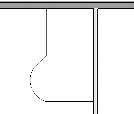
- Use the Add Break
 edit tool to add breaks along the edges of your polyline, which will allow you to then reshape the landing polyline.
- The Make Line/Arc
 edit tool can be used to convert a straight edge into a curved one, or vice versa.
- Use the Fillet Lines
 tool to fillet the corners of the landing polyline.
- Use the Chamfer Lines
 tool to chamfer the corners of the landing polyline.
You can find more information about these tools by referencing the program's Help documentation.
- Use the Add Break
- Select your tread and use the Transform/Replicate Object
 edit tool to open the Transform/Replicate Object dialog:
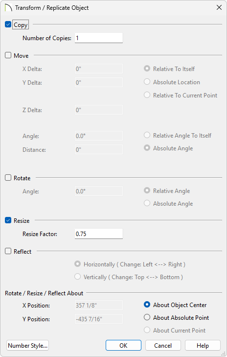
- Check the Copy box and set the Number of Copies to 1.
Note: If you're not creating custom treads that have curved/filleted/chamfererd edges it will be easier to use the Copy/Paste tool to create your copies. This Transform/Replicate method discussed here is quite useful for when you have curved treads, as it will keep the curve consistent across different sizes.
- Check the Resize box and set your Resize Factor.
In this example, we will use a Resize Factor of .75 to create a copy that is 75% of the original's size.
- Click OK to create a copy.

You can find more information about these options by referencing the program's Help documentation.
- Check the Copy box and set the Number of Copies to 1.
- Select the new landing and use the Open Object edit tool to open the Stair Landing Specification. On the General panel of the Stair Landing Specification:
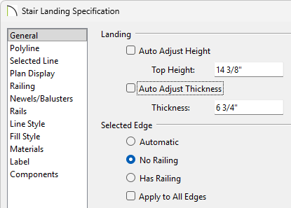
- Set the Top Height of the second tread to the Thickness + Top Height of the first tread. If working with a third tread, it would be the Thickness + Top Height of the second tread. This will position your tread perfectly atop the one below.
In this example, the first tread is 6 3/4" thick with a Top Height of 7 5/8", so we will set the top height of the second tread to 14 3/8". For the third tread, we will set the Top Height to 21 1/8" (14 3/8" + 6 3/4").
- Click OK to save your changes.
- Set the Top Height of the second tread to the Thickness + Top Height of the first tread. If working with a third tread, it would be the Thickness + Top Height of the second tread. This will position your tread perfectly atop the one below.
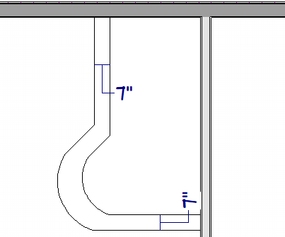
- Use the Temporary Dimensions to resize and position the landing.
In this example we will set the edges of our second landing 7" back from the first landing to create a 7" tread depth.
Alternatively, you can use the Point to Point Move edit tool, which will allow you to precisely position the edges of your treads.
When using Temporary Dimensions to adjust the new tread, you can select the Move Object behavior to move the object instead of resizing it. This will be useful for repositioning your custom treads that have curved edges.
- Repeat Steps 5-7 until you have your custom shaped treads created.
- Go to 3D> Create Perspective View> Full Camera
 and click and drag towards your custom treads to create a camera view. Ensure that your treads are how you expect and return to your floor plan view.
- Complete the rest of your staircase using landings, or if multiple treads are identical, use the dedicated Stair tool to crate a subsection of treads.
- Go to Build> Stairs> Draw Stairs
 and click and drag from the edge of your landing to create a staircase.
- If your custom treads require a railing, you can go to Build> Railing and Deck> Straight Railing
 to draw in a railing. Once the railing is set to follow the stairs, it will follow your custom treads.
For more information on drawing railings that follow your stairs/landings please see the Related Articles section.
- Go to Build> Stairs> Draw Stairs