Adding Detail to Customize a Porch
Pro | Architectural | Suite
QUESTION
I would like to add masonry and millwork details to the porch in my plan. What are some ways to do this?

ANSWER
Use items from the Millwork library to create custom details on the interior or exterior of your plan. In this example, we will use millwork items and soffits to customize a staircase and the railing of a porch.
To create a custom newel post
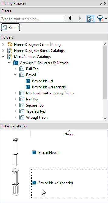
- In your desired plan, select View> Library Browser
 from the menu if the Library Browser is not already open, then browse to Home Designer Core Catalogs> Architectural> Millwork.
- When you find an item that suits your needs, click on it to select it.
- In this example, the Boxed Newel (panels) post from Arcways® Balusters & Newels manufacturer catalog is used.
For more information on downloading additional catalogs, such as the one mentioned above, please see the "Downloading and Updating Library Catalogs" resource in the Related Articles section below.
- When you find an item that suits your needs, click on it to select it.
- When you move your cursor into the drawing area, it displays the Millwork icon
 . Click once to place the item at the location where you clicked.
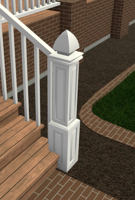
- Click on the newel post to select it, then use the Move
 edit handle that displays at its center to move the newel post into location at the bottom of the stairs.

- Select 3D> Create Camera View> Full Camera
 from the menu, then click and drag a camera arrow in the direction of the newel post.
In Home Designer Pro, navigate to 3D> Create Perspective View> Full Camera instead.
- In the 3D view, click on the newel post to select it, then use the edit handles to adjust its height and width.

- With the newel post selected, click the Open Object
 edit button.
- On the General panel of the Millwork Specification dialog:

- Make any needed adjustments to the Width, Height, and Depth of the post.
- Typically, the Width and Depth will have the same value.
- In most cases, the Floor to Bottom value should remain at 0.
- Click OK to close the dialog and apply your changes.
- Make any needed adjustments to the Width, Height, and Depth of the post.
- Still in the 3D view, select 3D> Material Painter> Material Eyedropper
 from the menu, then click on a staircase newel or baluster to load its material into the Material Painter. When you do so, your cursor displays the Material Painter
  icon.
icon.
- Click once on the newel post to apply the loaded material.

- When you are satisfied with the appearance of the newel post, select File> Close View to close the camera view and return to floor plan view.
To add a cap to a post or column
- In 2D floor plan view, access the Library Browser, then browse or search to find an item that meets your needs. When you find an item that suits your needs, click on it to select it.
In this example, the Finial 04 cap is used which can be located by navigating to Home Designer Core Catalogs> Architectural> Millwork> Finials & Caps> Finials within the Library Browser.
- Move your cursor
 into the drawing area, and click once on the newel post to place the cap on top of it.
- Click on the cap to select it, then use the Move edit handle that appears at its center to adjust its position so that it is centered over the newel post.
If you have trouble selecting the cap or any other object, click the Select Next Object edit button or press the Tab key on your keyboard until the desired object is selected.

- Select 3D> Create Camera View> Full Camera from the menu, then click and drag a camera arrow in the direction of the newel post.
In Home Designer Pro, navigate to 3D> Create Perspective View> Full Camera instead.
- In the 3D view, make any needed changes to the size or material of the cap as described in Steps 6 - 9, above.
- When you are satisfied with the appearance of the newel post and cap, select File> Close View to close the camera view and return to floor plan view.
To create masonry porch columns
The Soffit tool is ideal for any straight-sided object, such as a brick column. Intended primarily to fill the space between wall cabinets and the ceiling above, soffits are very versatile and can be used for numerous tasks.
- Select Build> Cabinet> Soffit
 from the menu, then click once in your plan near the porch to place a soffit at that location.
Alternatively, you can navigate to Home Designer Core Catalogs> Shapes> Boxes> Closed and use the closed box to create a column.

- Click on the soffit to select it, then click the Open Object edit button.
- On the General panel of the Soffit Specification dialog:

- Specify the Width, Height, and Depth of the column you wish to create.
- The Floor to Bottom value will probably be a negative number, which will extend the column below the porch, allowing it to reach the ground. The exact value will vary depending on the plan.
- When specifying the column Height, be sure that you take the Floor to Bottom value into account.
- On the Materials panel, click on the word Soffit with the rainbow icon beside it, then click the Select Material button and browse the Materials library category to find the material that suits your needs.
- Click OK to close the dialog and apply your changes.
- Specify the Width, Height, and Depth of the column you wish to create.
- Again, click on the soffit to select it, then use the Move edit handle to move it into position at one corner of the porch.
To move the soffit into the same space as the porch railing and floor, hold down the Ctrl/Command key on your keyboard while moving it.
- Masonry columns typically support posts that extend to the ceiling. Specify that your porch railing has posts by selecting a railing and then clicking the Open Object edit button.
- On the Rail Style panel of the Railing Specification dialog:

- Select either Post to Beam or Post to Ceiling.
- On the Newels/Balusters panel, specify the desired Newels/Posts Spacing, which also determines the spacing of posts.
- Click OK to close the dialog and apply your changes.
- Repeat this step for each porch railing in your plan.
- Select either Post to Beam or Post to Ceiling.
- In floor plan view, access the Library Browser once again, then browse to the Millwork category.
In this example, a Cap 03 is placed over the masonry column and the Rustic corbel is placed at the top of the railing post.
- In both floor plan view and 3D views, make any needed adjustments to the size, material and/or position of the group-selected objects, as described earlier in this article.
- When the column, cap and corbel are edited and in position, click the Select Objects
 tool, then Shift + select the three objects as described in earlier in this article.
- When the three objects are group-selected, click the Copy/Paste
 edit button, then click on the Sticky Mode
  edit tool.
- Click along your porch railing to place a masonry column, millwork cap, and corbel at each location.
- When you are finished, click the Select Objects tool to deactivate the tool.
- Click along your porch railing to place a masonry column, millwork cap, and corbel at each location.
- Select 3D> Create Camera View> Perspective Full Overview
 from the menu to see the results.
In Home Designer Pro, navigate to 3D> Create Perspective View> Perspective Full Overview instead.
