Creating a Log Cabin in Home Designer
Pro | Architectural
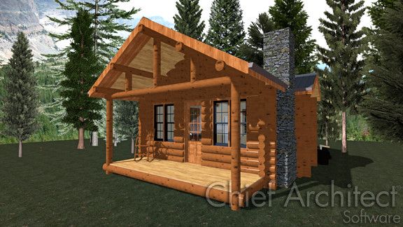
QUESTION
I would like to know how to model a log cabin building. How can this be accomplished?
ANSWER
With the external shell of this sample structure complete, a good place to begin with modelling the log is by placing log corners.
To apply log corners to the exterior
- Select 3D> Create Camera View> Perspective Full Overview
 so that you can see the exterior of your structure.

- Select Window> Tile Vertically
 so that you can see both your 2D Floor Plan view, as well as the 3D Camera view of the exterior of your structure.
- Next, select View> Library Browser
 and navigate to Exteriors> Exterior Attachments> Log Siding Pieces.
- Click on the entry for '8-13 Full' to select it, and in floor plan view, click near one of the outside corners of your structure to place the corner logs at that location.
- Next, select the symbol for '8-13 Half' and click to place this object around the corner from where the 8-13 Full was placed.
- Adjust the positions of these two log corners so they line up properly. In floor plan view, the corners will look like this:

In camera view, the corners look like this:

- Repeat this process for the remaining corners of the structure, making sure that 8-13 Full and 8-13 Half corners do not share the same wall, but are always around the corner from one another.
To apply log facade between the corners
With the log corners in place, the walls can now be faced with logs - or more accurately, half logs.
- In the still open Library Browser , notice that there are two '8-13 Facade' objects in the Logs library: 8-13 Facade and 8-13 Facade w/ Halves.
Place 8-13 Facades on walls that have 8-13 Half corners on them; and 8-13 Facades w/ Halves, on walls that have 8-13 Full corners.
- Select the symbol for 8-13 Facade and click once in floor plan view to add it to your drawing.

You can click anywhere in floor plan view to place it; however, if you click close to the exterior of a wall, it will automatically snap onto the wall's surface with the flat side facing inward and the log facade facing outward.
- By default, the 8-13 Facade is 36 inches wide; however, it can be quickly and easily resized in a 3D camera view.

While in a 3D view, select the facade and use the edit handles that display to stretch it so that it covers the entire wall.
If you find that the edges of the facade do not join up with the log corners, hold down the Ctrl key on your keyboard while dragging one of the side edit handles, which allows you to move or resize objects through obstructions.
- Repeat this procedure on all four sides of the structure, using the edit handles to resize the facades so that they fit the spaces properly.

To complete the exterior, you need to fill in the areas under the door and windows, and in the gable area, which can be accomplished using individual horizontal logs.
To place individual logs
- Return to the Logs catalog, then select the symbol for 8" Horiz, and click a number of times away from a wall in floor plan view to create a series of individual horizontal logs, as in the example below.

Extra logs can be deleted later; for now, though, we want plenty of logs so that we can then edit them as efficiently as possible in 3D view.
- To place these logs on the structure, both their size and position must be adjusted piece by piece.
- Adjust the height and length of each log in 3D view and then slide them into place on the wall and adjust their length in floor plan view.
- Once you have one log placed, you may find it helpful to use the Copy and Paste in Place
 edit tool to create a copy of the log at the same location, which you can then click and drag it up, or down, and bump into place to create another log already the correct length, such as when filling in space below and above windows.
- You can also group select these individual logs and use the Make Architectural Block
 edit tool to group them together into a single unit. This allows you to copy and paste to quickly fill in areas with the same gap (such as below windows of the same height, or to fill in an identical opposing gable end).
- Adjust the height and length of each log in 3D view and then slide them into place on the wall and adjust their length in floor plan view.
- For fine height adjustments, you can also select a log in the 3D view and click the Open Object
 edit button to open the Fixture Specification dialog, which allows you to specify a Floor to Bottom height.
In addition to placing log fixtures, there are also a selection of Log Siding materials in the Library Browser that can approximate the look of a log home without manually placing symbols.