Automatically Building a One and a Half Story Roof
Pro | Architectural | Suite
QUESTION
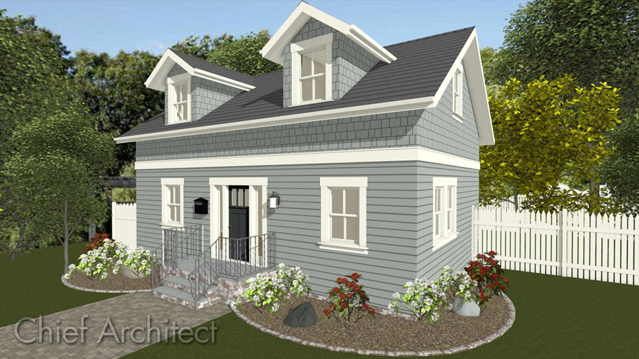
I want to create a Cape Cod style house, sometimes called a story and a half or an attic loft. How can I create this in Home Designer?
ANSWER
There are two ways to create a Cape Cod style house; with the roof sitting directly on top of the 1st story walls or with the roof sitting on knee walls a set distance above the second story floor.
For the purposes of this example, both techniques start with a 30' x 40' building.
To build a second floor with gable walls
- From the menu select Build> Floor> Build New Floor
 .
.
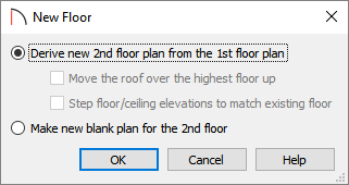
- In the New Floor dialog, choose the option to Derive new 2nd Floor plan from the 1st Floor plan, and click OK.
- The 2nd Floor Defaults dialog will display. Click OK in this dialog without making any additional changes at this time.
- On the newly created Floor 2, use the Select Objects
 tool to click on the left wall of your rectangular structure, then click on the Open Object
  edit button.
- On the Roof panel of the Wall Specification dialog, select the Full Gable Wall option, then click OK to close the dialog and apply your change.
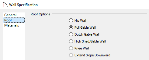
- Repeat this process for the right wall on your second floor as well.
If the design calls for the roof to be built directly off of the 1st floor walls but retain a usable attic space, you will need to generate roof planes that ignore the top floor. If this is the case, you will need to repeat steps 4 through 6 on the first floor walls.
To build a roof ignoring the top floor
- From the menu click Build> Roof> Build Roof
 .
.
- On the Roof panel of the Build Roof dialog, check Ignore Top Floor, then click OK.
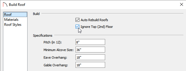
Note: In Home Designer Pro, this setting is located near the center of the dialog rather than towards the top.
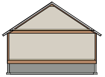
If the plan design calls for a roof structure that is built up to a specific height on knee walls, you will need to adjust the height of the second floor walls, then rebuild the roof.
To adjust the second floor to accommodate knee walls
-
Using the Select Objects
 tool, click inside of the second floor room to select it, then click the Open Object
  edit button.
- On the Structure panel of the Room Specification dialog, set the Finished Ceiling height to that which you want the exterior walls to be, then click OK.
For the purposes of this example, this is set to 24".
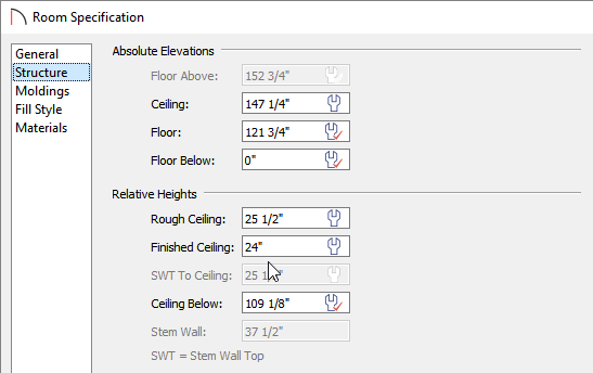
The appearance of the dialogs may vary depending on what version of Home Designer you're using.
- Select Build> Roof> Build Roof
 from the menu to display the Build Roof dialog:
- Uncheck Auto Rebuild Roofs so that the program will not automatically rebuild the roof if you make future changes that affect the roof, such as to exterior wall positions or ceiling heights.
- Specify the Pitch (in12).
- If you are using Home Designer Pro, check the box by Build Roof Planes.
- Verify that the Ignore Top Floor option is not checked.
- Uncheck Auto Rebuild Roofs so that the program will not automatically rebuild the roof if you make future changes that affect the roof, such as to exterior wall positions or ceiling heights.
- Click OK to confirm the changes and notice that the newly regenerated roof accommodates the 24" high knee walls on the second floor.
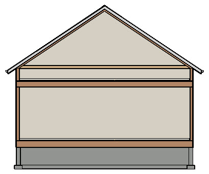
Now that we have created our roof at the correct height for our story and a half structure, we are ready to set the Finished Ceiling height back to its default value.
Resetting the finished ceiling height
-
Use the Select Objects
 tool to click inside of the second floor room once again, then click the Open Object
  edit tool to again display the Room Specification dialog.
-
On the Structure panel, click the wrench icon in the Finished Ceiling field to change this back to the default value.

-
Click OK to close the dialog and apply the change.

Dotted lines display on the plan indicating where the ceiling planes intersect the roof.

-
You are now ready to furnish the area, or take the information that you have learned in this article and apply it to your own design.