Modeling a Subdivision or Lot with Multiple Structures in Home Designer
Pro | Architectural
QUESTION
On many occasions I have used Home Designer to construct a single building. However, today I would like to create a subdivision. How do I accomplish this?
ANSWER
When creating subdivisions, or other large projects, it is important to remember that Home Designer is designed to create a single home in a single drawing. However, there is no set limit to the number of homes that may be included in any one drawing.
Recommendations to customers who want to use Home Designer to design a subdivision or a small town include:
- Model each single family home in it's own plan file. Eventually, each customer you work with will require customization and changes to their particular home. Also, you will need to print their plans to obtain permits. Both of these tasks are made easier if you only have one house in a drawing.
- The subdivision itself should be in a separate drawing in which you model the terrain, streets and sidewalks, and other features of the development.
- Export each house plan out of Home Designer as a 3D model and then import each model into the subdivision file. Within the subdivision file, model files can be positioned as needed.
To export a plan or structure as a 3D model
-
Open
 the Home Designer plan that you would like to convert into a 3D model.
- Select 3D> Create Camera View> Perspective Full Overview
 from the menu to create a camera view of the entire structure.
In Home Designer Pro, navigate to 3D> Create Perspective View> Perspective Full Overview instead.
- Select Tools> Display Options
 from the menu.
- In the Display Options dialog that opens, scroll down the list of layers and ensure that the items you want to have displayed, such as walls, doors, and windows, have a checkmark in the Disp column.
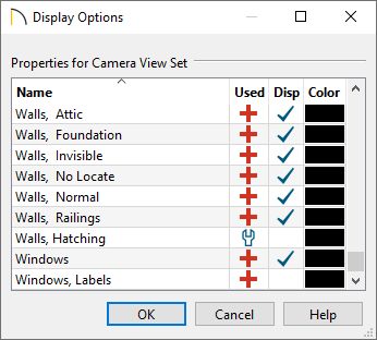
- Uncheck the display of any layers that you don't want displayed for the model that will exported.
- Unchecking the "Furnishings, Interior" and "Fixtures, Interior" layers will help minimize the number of surfaces your model will have and improve rendering time for the subdivision. However, interior fixtures and furniture will not be present when viewing the model in the subdivision file.
- Be sure to turn off the display of all terrain layers.
- Unchecking the "Furnishings, Interior" and "Fixtures, Interior" layers will help minimize the number of surfaces your model will have and improve rendering time for the subdivision. However, interior fixtures and furniture will not be present when viewing the model in the subdivision file.
- When you are satisfied with the layer settings, click OK.
- Next, navigate to File> Export> Export 3D COLLADA Model (DAE)
 from the menu.
- Specify a file name and a location in the dialog that appears next, then click Save to export the model.
When exporting a COLLADA (DAE) model, a .dae file will be created, along with a folder containing the model's textures. It's important to keep the textures folder in the same location as the .dae file.
- Repeat steps 1-8 for any additional plans that you would like to be part of the subdivision.
To create the subdivision file and import the models
- Create a New Plan
 , then choose to Save
  the file.
- Within a floor plan view, navigate to File> Import> Import 3D Symbol
 from the menu.
- Browse to where you saved the .dae model file, select it, then click Open.
- In the Symbol Specification dialog that appears next, verify that the model looks correct, and that the Materials are set correctly, then click OK.
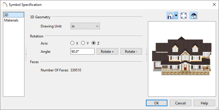
- Next, click in the plan to place the model.
Note: Models such as this will be imported as fixtures. Once placed, the model can be opened and edited further within the Fixture Specification dialog.
Additionally, the model can be added to the User Catalog section within the Library Browser using the Add to Library edit tool.
- Repeat this process for any other additional models that you would like to add to the design.
- Finally, create a Terrain Perimeter, and add in elements such as roads, sidewalks, and other terrain features.