Drawing a Shed Dormer Manually
The information in this article applies to:

QUESTION
How can I manually create a large shed dormer roof in my plan?

ANSWER
This article will walk you step-by-step through creating a basic plan with a manually drawn shed dormer. Once you have completed the tutorial, you can take this information and then apply it to your own designs.
To create the basic structure
- Begin by creating a basic 40' x 30' structure on Floor 1.
- Using the Select Objects
 tool, select the 30' wall on the left, and click on the Open Object
  edit button.
- On the Roof panel of the Wall Specification dialog that displays, select the Full Gable Wall option and click OK.
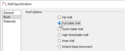
- Repeat this process for the right wall, so that both 30' walls are marked as Full Gable Walls.
Once you have done this, you are ready to create the second story where the manually drawn shed dormer will be created.
To create the second floor
- Select Build> Floor> Build New Floor
 , choose to Derive new 2nd floor plan from the 1st floor plan, then click OK to display the Floor 2 Defaults dialog.
- Without making any changes, click OK in the 2nd Floor Defaults dialog to generate your second floor, based on the walls from Floor 1.
Now you are ready to create the knee walls in your plan.
Knee Walls are a bit like Attic Walls in that they are not meant to generate to full ceiling height. Instead, they build upward until they encounter a roof plane. Unlike Attic Walls, however, Knee Walls are used in the interior of a structure, typically to separate unused areas from rooms on the upper floor of a story-and-a-half structure.
Home Designer will not specify walls as Knee Walls automatically. So, if an interior wall is drawn in a location where the roof is lower than the ceiling height, you should specify it as a Knee Wall in the Wall Specification dialog.
To create the knee walls
- Select Build> Wall> Straight Interior Wall
 then click and drag out two interior walls, as shown in the image below.
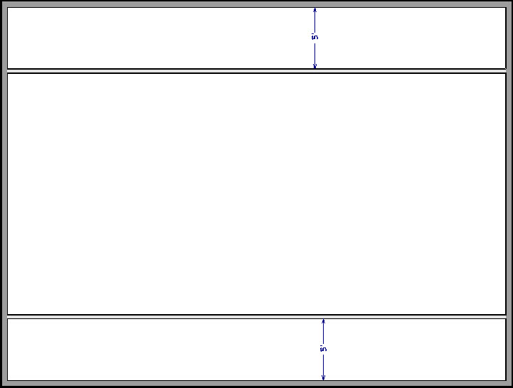
- For the purposes of this example, the interior walls were created 5' away from the exterior walls.
- Next, use the Select Objects
 tool to select one of the interior walls, and click on the Open Object
  edit button.
- On the Roof panel of the Wall Specification dialog that displays, select the Knee Wall option and click OK.
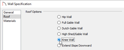
- Repeat this process for the opposite interior wall, so that both are marked as Knee Walls.
Now that you have your knee walls defined, you are ready to create the walls for your shed dormer.
To create the dormer walls
- Select Build> Wall> Straight Exterior Wall
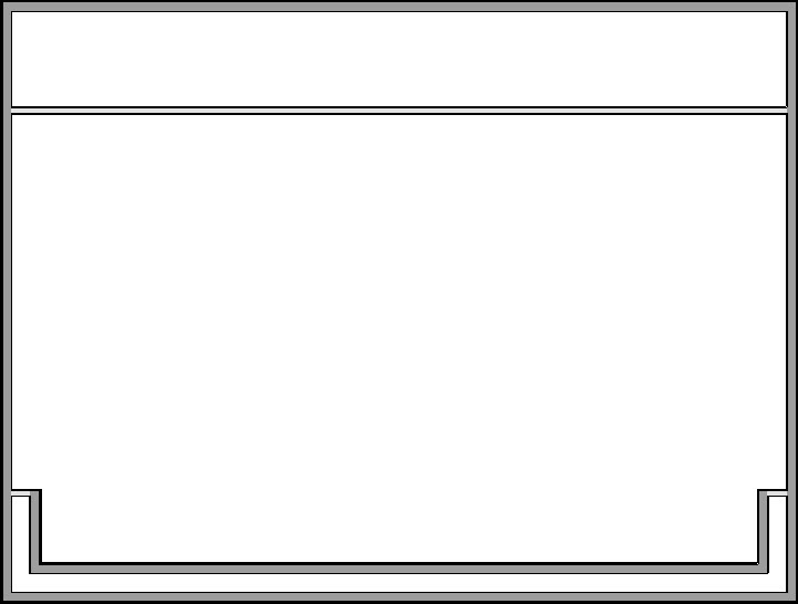
 and draw a rectangular box in a clockwise direction on the outside of the lower interior wall, as shown in the following image.

- Position the lower wall of the dormer box 1 foot from the bottom wall, and edit the box so that it is also 1 foot from each vertical side wall.
- Next, select Build> Wall> Break Wall
 and click along the lower interior wall to place wall breaks as indicated by each oval in the following image.

- Delete the upper, horizontal portion of the box.
- Next, since you will want this dormer to be a shed dormer, select the left exterior wall segment of the dormer, open its Specification dialog, and mark it as a Full Gable Wall as well.
- Repeat this process for the right dormer wall, so that both are marked as Full Gable Walls.
- Finally, on the front wall of the dormer, open its Specification dialog and define the pitch to be less than that of the normal roof you will generate over the design, then click OK to apply the change.
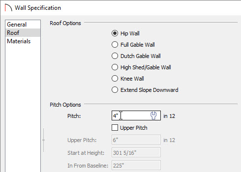
- For the purposes of this example, define this wall as having a pitch of 4" in 12.
Now you are ready to define the upper and lower rooms as Attic space, so that these areas will be ignored by the program’s automatic roof generator.
To define the Attic rooms
- Use the Select Objects
 tool to select the northernmost room area on the 2nd floor, and click on the Open Object
  edit button.
- On the General panel of the Room Specification dialog that displays, specify the Room Type as Attic, then click OK.
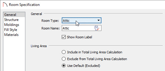
- Repeat this process for the lower Attic room as well
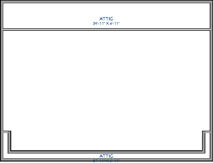
You may receive a Warning dialog regarding knee walls. If so, click OK and continue onto the Roof section.

Now both the upper, and lower room areas should be defined as Attic, with the middle section remaining undefined for now.
To adjust the roof
- To adjust the roof settings, select Build> Roof> Build Roof
 from the menu.
- In the Build Roof dialog that displays, ensure that either Build Roof Planes or Auto Rebuild Roofs is checked, specify your desired Pitch (in 12), then click OK.
- For the purposes of this tutorial, the Pitch (in 12) value is set to 12".
Note: These specifications were used specifically for the plan in this tutorial. If you are designing a building and find that it does not build as expected, you may need to increase the roof pitch or lower the room's height to accommodate the roof height.
- Next, create a 3D Camera
 view to see the results.
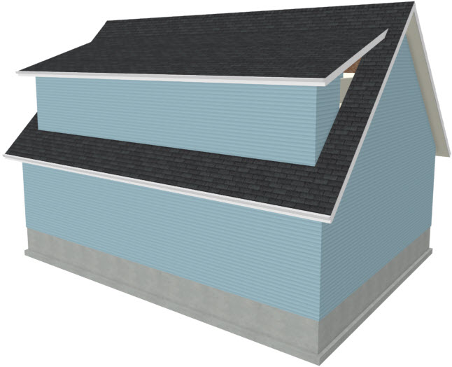
- Notice there are small gaps in the dormer side walls. These gaps are caused by the difference between the position of the knee walls, and the point at which the ceiling intersects the roof plane. This location is marked by the black dotted line in floor plan view.
- Select Window> Tile Vertically
 so that you can see both your 3D Camera view side by side with your 2D floor plan view.
- In floor plan, select each of the knee wall segments related to the dormer and move them back so that they are in alignment with the ceiling plane.
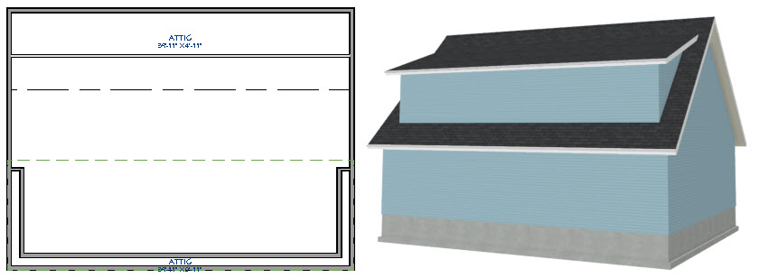
- The walls will snap into position when they are close to the ceiling lines.
- Next, take another look at the 3D Camera view to see that the gaps have closed.
- You can move the interior walls closer to or further from the outside walls to change the dormer's elevation, or change the pitch for the roof to make the dormer longer.
- If there is attic space above the dormer, it may be necessary to modify the attic walls on Floor A as well as the dormer walls on Floor 2.
- You can move the interior walls closer to or further from the outside walls to change the dormer's elevation, or change the pitch for the roof to make the dormer longer.
You can create dormers in more complex plans the same way, but you may want to experiment with wall placement and pitch to achieve the desired effect.
To add windows
- Select Build> Window> Window
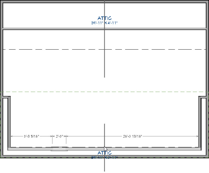
 and click on the dormer front wall to place a window.
- Select the window, click the Center Object
 edit button, and click near the wall containing the window to center it on the wall.
- Next, click on the Open Object
 edit button, and in the Window Specification dialog that displays, specify the Window Type, Width, Height, and other properties to your liking.
For the purposes of this tutorial, the Window Type is set to Fixed Glass, the Width is set to 35', the Height is 48", and the number of Lites Across is set to 8, while the Lites Vertical is set to 2.
- When you have completed making changes, click OK to close the dialog and apply them.