Creating a Split Level Structure
The information in this article applies to:

QUESTION
How do I create a split level floor plan?

ANSWER
A split level, sometimes referred to as a bi-level or tri-level, is a building where the floor level in one part of the structure is located about halfway between the floor and ceiling levels of another part of the structure.
You can easily create a split level in Home Designer by controlling the floor and ceiling heights of different rooms in a plan.
To create a split first floor level
- Launch Home Designer and create a New Plan
 .
.
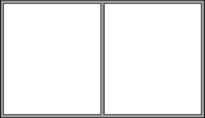
- Select Build> Wall> Exterior Wall
 , then click and drag to draw a simple rectangular structure.
- Still using the Exterior Wall tool, draw a wall that divides the structure into two rooms.
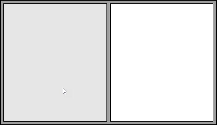
- Click the Select Objects
 button, then click in an empty space in one of the two room areas of your drawing to select it.
In this example, the room on the left side is selected.
- Click the Open Object
 edit button, and on the Structure panel of the Room Specification dialog:
- Raise the height of Floor (C). In this example, this value is increased to 48".
- Press the Tab key on your keyboard to update the dialog and notice that the Relative Ceiling heights become smaller.
- Check the Default box next to Rough Ceiling (E) and press the Tab key to restore a full height ceiling to this room.
- Click OK to close the dialog and apply your change.
- Raise the height of Floor (C). In this example, this value is increased to 48".
- Select 3D> Create Camera View> Doll House View
 to see the results so far.
- The wall that divides the structure into two halves should have its exterior siding surface facing the room with the lower floor height.
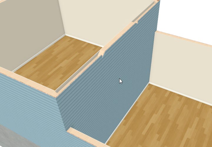
- If it does not, click the Select Objects button, then click on the wall.
- The room will be selected first - press the Tab key or click the Select Next Object
 edit button to select the wall instead.
- With the wall selected, click the Reverse Layers
 edit button.
- If it does not, click the Select Objects
To modify the foundation
In a split level home, part of the foundation is typically a slab or crawl space and part is full height basement - often a daylight basement.
- Select Build> Floor> Build Foundation
 from the menu to open the Build Foundation dialog. On the Foundation panel:
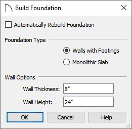
- Uncheck Automatically Rebuild Foundation.
- Select Walls With Footings as the Foundation Type.
- Specify the Wall Height. In this example, a height of 24" is used.
- Make any other needed changes, then click OK, then OK again to close the dialog and modify the foundation on Floor 0.
- Uncheck Automatically Rebuild Foundation.
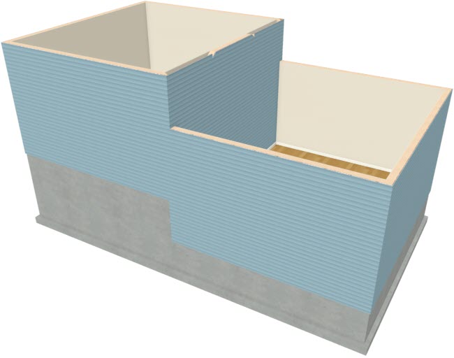
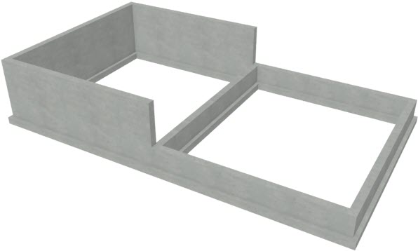
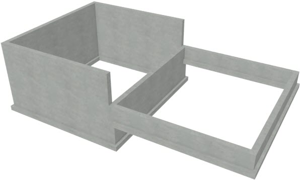
- While still on Floor 0, create a Doll House View to see what this foundation looks like.
Notice that the Minimum Stem Wall height is applied to the part of the structure with the lower, default floor height. The stem walls under the area with the raised floor are taller but have the same footing height.
- Click the Select Objects button, then click on an inside wall surface of the foundation room, below the part of the structure with the raised floor height (in this example, the left side).

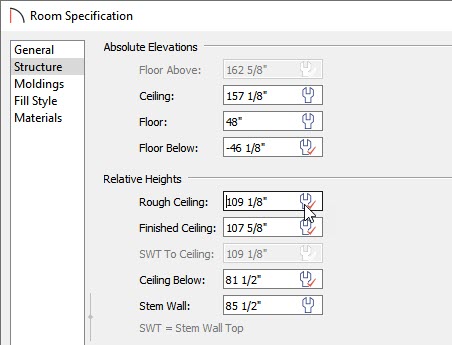
- Click the Open Object edit button, and on the Structure panel of the Room Specification dialog:
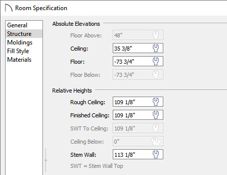
- Notice that the Stem Wall height value is equal to the Minimum Stem Wall Height that you specified in the Build Foundation dialog plus the height of the Floor of the room above.
- Increase the Rough Ceiling value so that the room is full height. In this example, it is raised to 109 1/8".
- Press the Tab key and notice that the Stem Wall height increases to accommodate the new ceiling height.
- Click OK to close the dialog and apply your change.
- Notice that the Stem Wall height value is equal to the Minimum Stem Wall Height that you specified in the Build Foundation dialog plus the height of the Floor of the room above.
- The Floor Overview updates to show the change that you made to the room.
- Select File> Close View to close the camera view and return to floor plan view.
To add a second floor
If you build an additional floor above the first floor level, bear in mind that the ceiling heights on Floor 1 will be reset to the default.
- Select Build> Floor> Build New Floor
 from the menu.
- Derive new 2nd floor plan from the 1st floor plan.
- Specify the desired default Ceiling height in the Floor 2 Defaults dialog.
- Derive new 2nd floor plan from the 1st floor plan.
- Go Down One Floor
 to Floor 1, then select the room with the raised Floor height and click the Open Object edit button.
- Notice that its Absolute Ceiling height has been reset to the default.
- Check the Default box beside Rough Ceiling and click OK.
- Notice that its Absolute Ceiling height has been reset to the default.
- Go Up One Floor
 and repeat this process for the room area directly above the one you just modified.
- Once all floor levels are in place and the ceiling heights are specified as needed, you can modify the roof and draw interior walls.