Creating Stairs in Sloping Terrain
Pro | Architectural | Suite
QUESTION
I would like to draw a set of stairs that cuts into sloping terrain to join two sidewalks, but when I draw stairs in my plan, they do not follow the terrain or join to my sidewalks. What should I do?

ANSWER
You can create stairs that follow your terrain by drawing the stairs in an area defined by Retaining Walls and snapping the stairs to landings at each end.
The first step to creating stairs that follow the terrain in a plan is to create the landings that the stairs will attach to. We can define the heights of these landings to control the staircase's height, as well.
terrain stairs
To create stair landings
-
Open
 the plan in which you want to create stairs in sloping terrain.
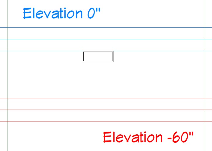
In this example, the terrain has a single slope between two flat areas.

- Select Tools> Display Options
 from the menu and turn off the display of the "Terrain, Primary Contours" layer.
Note: While not strictly necessary, this will make drawing in the sloped area of the terrain easier.
To learn more about toggling the display of objects, please see the appropriate resource located in the Related Articles section below.
- Select Build> Stairs> Landing
 from the menu, then click and drag to draw a landing in the area of your plan where the stairs will be located.
-
Using the Select Objects
 tool, click on the landing, move it if needed using the Move
  edit handle, and edit the size and shape as needed using the other landings edit handles.
- Once the landings shape is to your liking, select it once again and click the Open Object
 edit button.
-
On the General panel of the Stair Landing Specification dialog that displays:
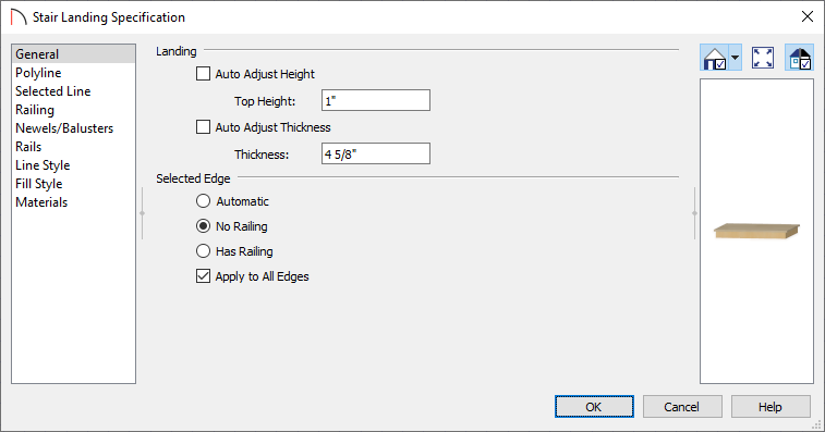
- Uncheck Auto Adjust Height and set the Top Height to match the height of the terrain or feature.
For this example we will be setting it to 1".
Note: When a building is present in a plan, the Top Height value of a stair landing is measured relative to the Default Floor Height for Floor 1, which is defined as 0".
Bear in mind that this 0" value is not the same as 0" in the terrain if you have a building drawn in your plan. The program will automatically drop the terrain relative to the height of Floor 1, depending on the type of foundation that you build.
- Uncheck Auto Adjust Thickness and specify a Thickness value you would like to use.
In this example, a value of 4 5/8" is used.
- Set whether or not you would like railings to be created on the selected landing edge or for all edges.
For this example, we don't want any railings, so we selected the No Railing radio button and checked the Apply to All Edges checkbox.
- Select the Materials panel to change the materials used for the landing.
- Click OK to confirm all of your changes and close the dialog.
- Uncheck Auto Adjust Height and set the Top Height to match the height of the terrain or feature.
-
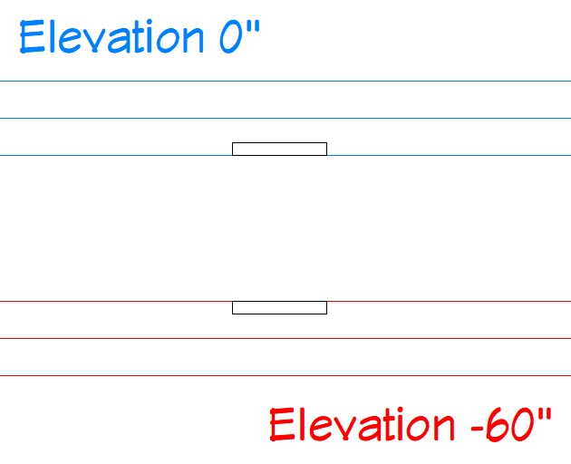
With the landing still selected in a plan view, select the Copy/Paste
 edit button, then click where you'd like to place a second landing at.
In this example, we will have a landing at the top of the stairs and one at the bottom.
-
Using the Select Objects tool, select the copied landing, click on the Open Object edit button to open it up the Stair Landing Specification, and adjust the Top Height and Thickness.
In this example, the second stair landings top height value is set to -59" and the thickness is set to 1".
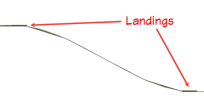
- Take an Orthographic
 view to check the heights of your landings relative to the terrain. If the landings and terrain are not near one another, return to floor plan view and make any necessary adjustments to the landing floor heights. Depending on the requirements of your drawing, you may need to make changes to your slope, instead.
To draw stairs between landings
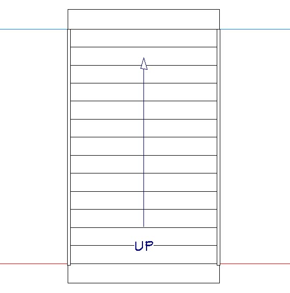
- Select Build> Stairs> Draw Stairs
 from the menu, and click and drag to create a set of stairs starting from the lower landing and ending at the top landing. A staircase will be created and the width will adjust to the width of the landings if they snap to each other.
Note: If the staircase doesn't adjust to the width of the landings, select the top/bottom edge of the staircase and adjust it so it stops and snaps to the edge of the landing(s).
- Using the Select Objects tool, select the staircase and use its edit handles to make any desired adjustments to its position. The landings will also move with the stair.
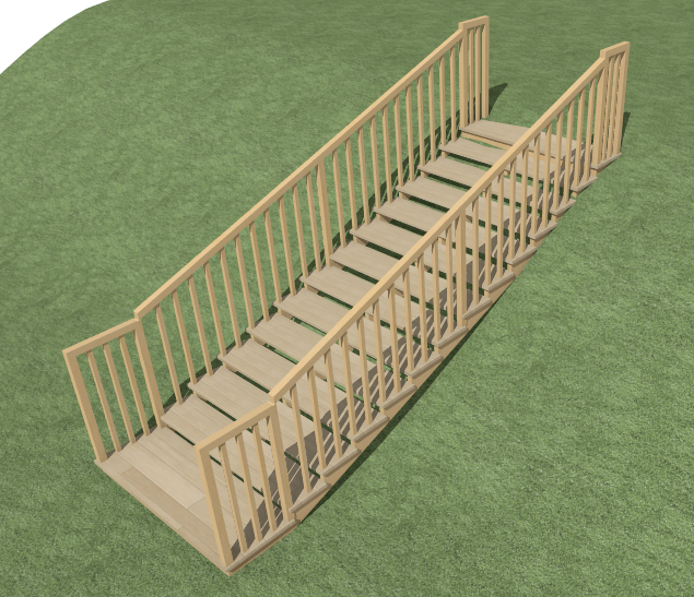
- Take a Camera
 view to see the results.
If the terrain spills into the staircase, consider using a terrain hole to cutout the terrain where the stairs are located. Navigate to Terrain> Feature> Terrain Hole ![]() while in a floor plan view, then click and drag to create a terrain hole encompassing the staircase.
while in a floor plan view, then click and drag to create a terrain hole encompassing the staircase.