Creating a Manual Wall Dormer
Pro
QUESTION
How do I create a manual dormer, such as a wall dormer in Chief Architect?

ANSWER
Many dormer types can be created automatically using the Auto Dormer tools. There are, however, some situations where dormers must be drawn manually. A wall dormer is a prime example.
To learn more about the Auto Dormer tools to create various types of roof dormers, please view the "Creating an Automatic Dormer" resource in the Related Articles section below.
To draw the dormer walls
- Access the plan in which you want to build a manual wall dormer.
In this example, we will be using a 30' x 40' structure with a Cape Cod roof at a pitch of 8" in 12.
For information about creating a Cape Cod or a story and a half roof, see the Related Articles section below.

- In floor plan view, select Tools> Floor/Reference Display> Up One Floor
 from the menu to go to the second floor.

If your roof planes are not displayed on the floor level the dormer will be created on, navigate to the floor level where they are currently displayed, select the roof plane(s), and click the Display on Floor Above or Display on Floor Below
  edit tool(s).
Note: The dashed lines in the image above represent ceiling break lines and will display when the pitch of the ceiling changes. Ceiling break lines cannot be selected, however, they can be hidden by turning off the "Ceiling Break Lines" layer.
- Select Build> Wall> Exterior Wall
 and draw two walls that will serve as the dormer's side walls, making sure that the exterior layer of each wall is facing outward.
Note: If a wall is not oriented correctly, select it using the Select Objects tool, then click on the Reverse Layers edit tool.

- Adjust the position and length of each wall to your liking.
In this example, each dormer wall is 9' 6" in length and they are positioned approximately 11' apart.

- Next, select one of the dormer walls, click the Open Object
 edit button, and in the Wall Specification dialog that displays:
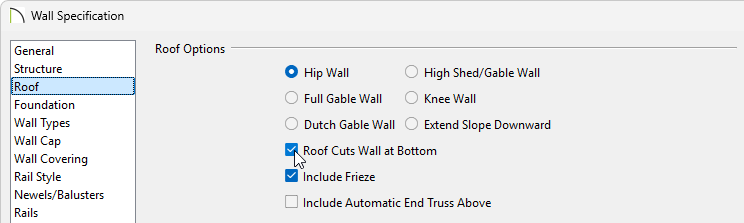
- Select the Roof panel and place a check in the Roof Cuts Wall at Bottom box.
- Click OK to close the dialog.
- Select the Roof panel and place a check in the Roof Cuts Wall at Bottom box.
- Repeat Step 5 on the opposite dormer wall.
To build the dormer's roof
- Using the Select Objects
 tool, click on the existing roof plane that is currently above the dormer walls, then select the Add Break
  edit tool.
-
Click to place break points where each wall meets the roof plane.
Note: Diamond-shaped edit handles will appear designating a break point in a polyline-based object.

- With the breaks placed, adjust the roof plane so it no longer covers the dormer walls. The roof plane should be snapped to the outside of the wall's exterior layer - in this case, the siding layer.

- Select 3D> Create Perspective View> Perspective Full Overview
 to verify that the dormer walls are exposed and are not covered by any roof planes.

- Select File> Close View to return to floor plan view, select the roof plane again, then place an additional break point along the back edge of the roof plane that was adjusted in step 3 above.

- Drag the newly created break point towards the main ridge line to create a peak.

- Next, select Build> Roof> Roof Plane
 , and draw a small roof plane over each of the dormer side walls.
If the Set Baseline Height dialog appears, select Over Wall Top and click OK.

- Join the two dormer roof planes at the ridge:
- Click on the ridge edge of either dormer roof plane to select that edge.
- Click the Join Roof Planes
 edit button.
- Click on the ridge edge of the other dormer roof plane.

- Click on the ridge edge of either dormer roof plane to select that edge.
- Next, select the back edge of either dormer roof plane, click the Join Roof Planes edit tool, then click the corresponding angled edge of the roof plane that was adjusted in step 6 above. The roof planes will now be parallel to each other. Perform this same procedure for the the opposite dormer roof plane.

- Select 3D> Create Perspective View> Full Overview to see the results.

Note: It may be necessary to shorten or extend the length of the dormer walls depending on the pitch of the roof and how the ceiling is defined in this area.
You are now ready to add a window and other finishing touches.