Creating a Flat Parapet Roof in Home Designer
Reference Number:
KB-00120
Last Modified:
October 7, 2024
This article also applies to the following legacy products:
Pro | Architectural | Suite
Pro | Architectural | Suite
QUESTION
How do I create a flat roof with parapet walls?

ANSWER
Parapet roofs can easily be created by creating a second floor with no roof or ceiling.
To create a flat parapet roof
- In a new, blank plan, select Build> Wall> Straight Exterior Wall
 and draw four walls in a clockwise manner to create an enclosed rectangular structure.
-
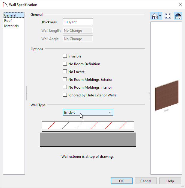
Open
 these walls up to specification, choose the desired Wall Type on the General panel, then click OK.
In Home Designer Pro, the wall type can be changed on the Wall Types panel.
In this example, the Brick-6 wall type is specified.
Note: To learn more about group selecting objects, please see the Related Articles section below.
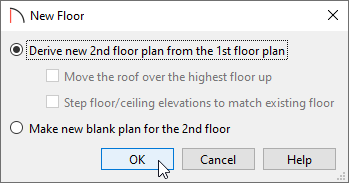
- Select Build> Floor> Build New Floor
 from the menu and in the New Floor dialog, choose Derive new 2nd floor plan from the 1st floor plan, then click OK.
- In the 2nd Floor Defaults dialog that displays next:
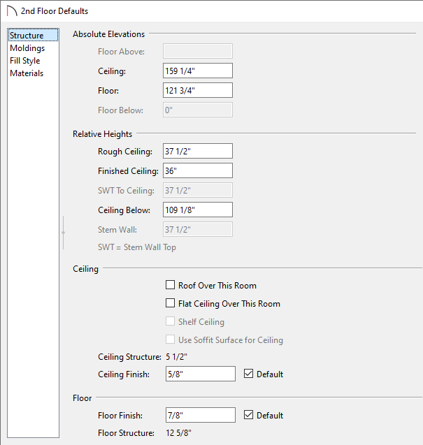
- On the Structure panel, specify the Finished Ceiling value to the height you would like for your parapet walls, then uncheck Roof Over This Room. The Flat Ceiling Over This Room setting will automatically become unchecked as well.
In this example, a value of 36" is specified.
- On the Moldings panel, adjust the moldings that are applied to the inside of the room.
In this example, no molding profiles are specified.
- On the Materials panel, adjust the Floor Finish material to your liking.
- Make any other desired changes, then click OK.
- On the Structure panel, specify the Finished Ceiling value to the height you would like for your parapet walls, then uncheck Roof Over This Room. The Flat Ceiling Over This Room setting will automatically become unchecked as well.
- With Floor 2 now active
 , group select the newly created walls, then click the Open Object edit button.
- In the Wall Specification dialog that displays:
- In Home Designer Pro, you can access the Rail Style panel, check the Specify Railing box, and set the type to Solid. By doing this, automatic wall caps will generate on each of the walls.
- On the Materials panel, change the Exterior Wall Surface, Interior Wall Surface, and Wall Cap (if applicable) materials to fit your needs.
- Make any other desired changes, then click OK.
- In Home Designer Pro, you can access the Rail Style panel, check the Specify Railing box, and set the type to Solid. By doing this, automatic wall caps will generate on each of the walls.
-
(Optional) Wall caps can be created manually using the Closed box located in the Library Browser. This is found by navigating to Home Designer Core Catalogs> Shapes> Boxes> Closed.
Once placed, the Width, Depth, Height, Floor to Bottom/Top, and Material can all be adjusted, effectively giving you the ability to create fully custom caps that can be placed on top of your parapet walls.
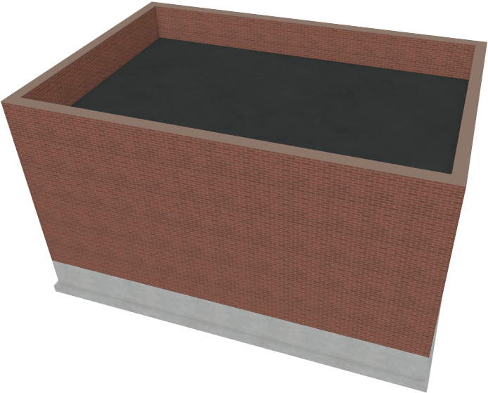
- Take a Camera
 view to see the results.
Related Articles