Creating Hip and Gable Roofs Manually
Pro
QUESTION
How can I manually create a Hip or Gable Roof?
ANSWER
In this tutorial, we will show you how to set your defaults for building a roof, how to manually draw roof planes to create a hip roof, and how to manually create roof planes for a gable roof.
Home Designer Pro also allows you to create roofs automatically. You can use the automatic roof tools to create hip or gable roofs. However, in some situations, you may find it is easier to create roofs manually.
To create manual roof planes
- First, launch Home Designer Pro, and select File> New Plan
 to create a completely new, blank plan with nothing yet drawn on it.
- Next, set your roof defaults by selecting Build> Roof> Build Roof
 to display the Build Roof dialog.
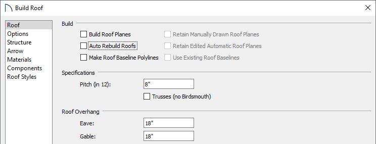
- Uncheck Auto Rebuild Roofs if it is checked.
-
- Set the Pitch (in 12) value to 6".
- Note that the Roof Overhang is set to 18". For this tutorial we will not be changing this, but it is important to remember for later steps.
- Select Build> Wall> Straight Exterior Wall
 and draw, in a clockwise fashion, a completely enclosed 4-wall rectangular structure.
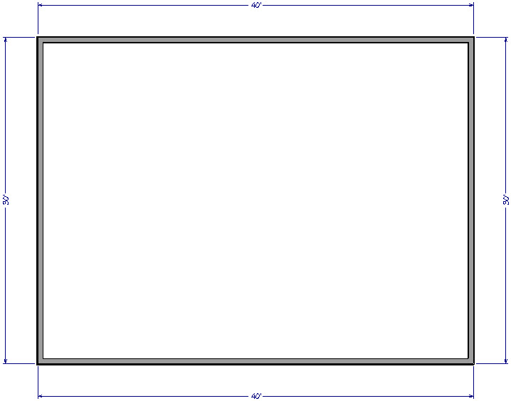
For the purposes of this example, our structure is 30' x 40'.
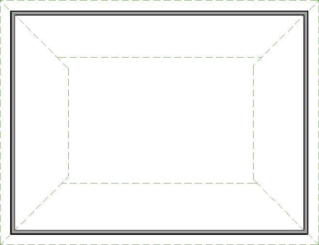
- Select Build> Roof> Roof Plane
 and click and drag a baseline across the length of a wall.
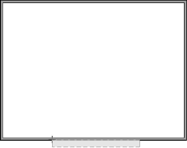
When creating a hip roof, be sure not to draw across the entire length of the wall, as you will need space on either end for adjacent roof planes.
- Release the mouse button and move your cursor in the upwards direction. As you move the cursor, a preview outline of the roof plane displays.
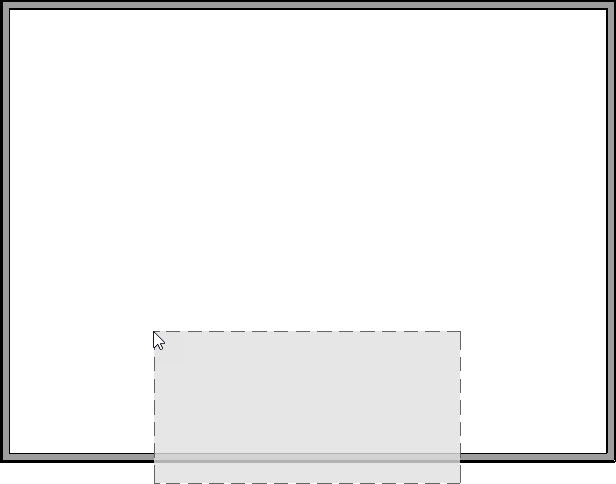
- Click inside the room to set the ridge edge of the roof plane, and complete your first roof plane.
A gable roof is created with two opposing roof planes that meet at a ridge.
To create a gable roof using manual roof planes
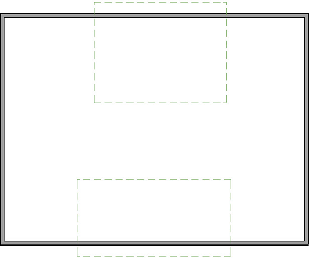
- Using the steps above, draw two opposing roof planes to create a gable roof.
- Use the Select Objects
 tool to select the top edge of the bottom roof plane.
- Click the Join Roof Planes
 edit button, then click on the bottom edge of the top roof plane to join to the selected edge of the first plane.
Note: To use the Join Roof Planes tool, you must first identify which edges of the roof planes can extend to meet at a ridge, hip, or valley. The program will try to join the two planes along the line where they intersect whenever possible.
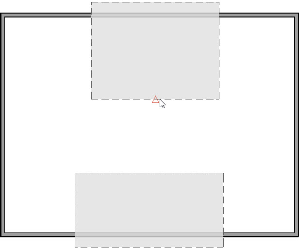
- You should now have two joined roof planes.
- Now extend the sides of each roof plane so that they extend past the exterior walls.
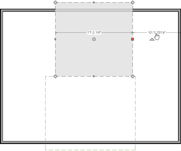
When we select the side of one of the roof planes we can see a temporary dimension line indicating its distance from the wall.
- By clicking on this dimension line, we can set the side of the roof plane's distance from the exterior of wall layer using the in-line text box that displays.
- The default overhang that we saw earlier in the Build Roof dialog was set to 18".
-
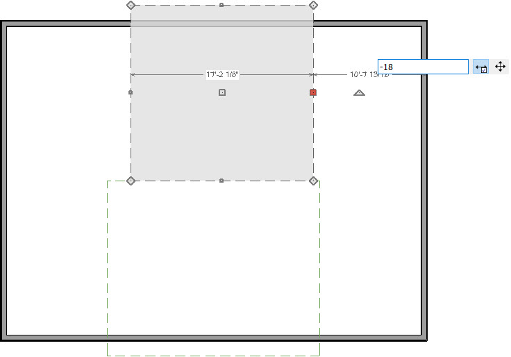
- If the overhang is set to 18 inches, the roof plane will be 18 inches from the outside of the wall. This is because it is being measured towards the inside.
- If we set the overhang to zero, the edge of the overhang would exactly match the outside of the wall.
- We want to measure 18 inches away from the exterior side, so we enter negative eighteen inches (-18") and press Enter.
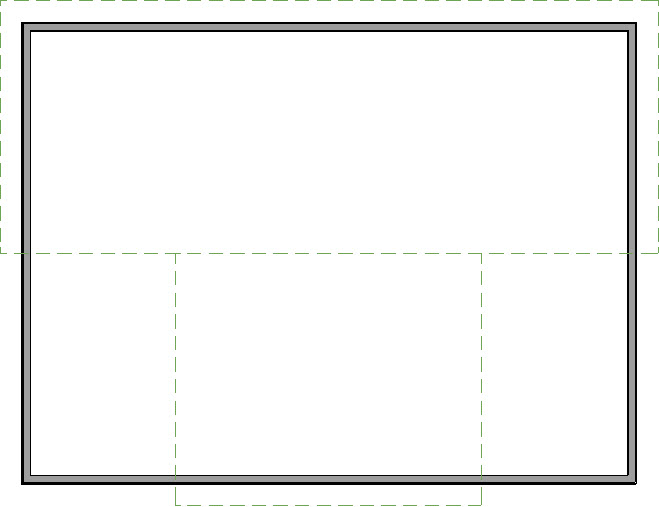
- Repeat this process for the other side of the upper roof plane.
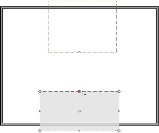
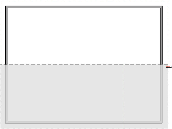
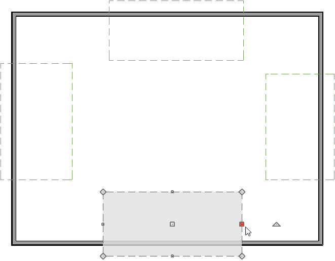
- You can repeat this same process for the bottom roof plane, or you can simply drag the edges to match the top roof plane. To do this, use the Select Objects tool to select the roof plane by clicking either side edge, select the Move
 handle, and drag until it snaps to the corner of the other roof plane. Note the red indicator box marking the snap point.
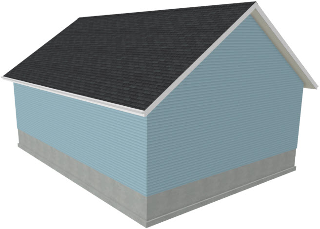
- Select 3D> Create Perspective Camera> Full Overview
 to see that we now have a completed, manually drawn, gable roof.
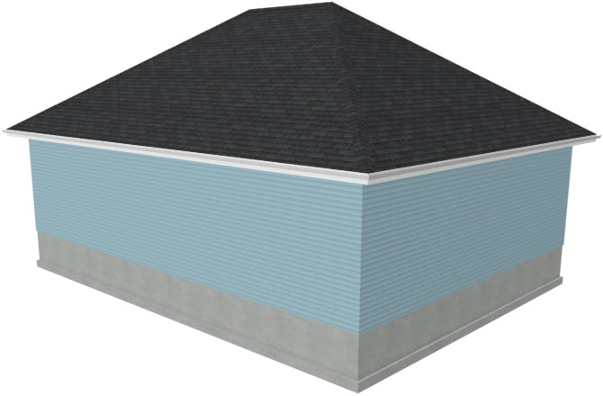
A hip roof has roof planes built over every exterior wall in the plan that does not have another wall drawn above it.
To create a hip roof using manual roof planes
- We will use the existing plan from the section above, but first we will need to delete the existing roof planes in our plan by selecting Build> Roof> Delete Roof Planes
 .
.
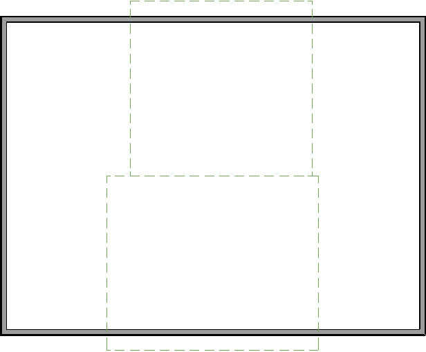
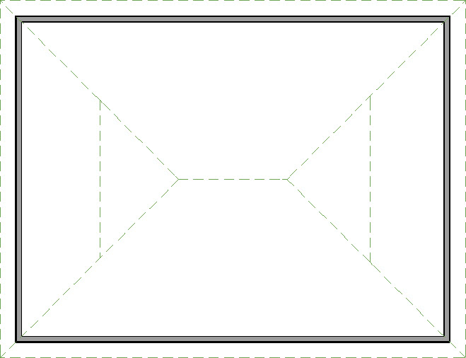
- Draw manual roof planes over each exterior wall of the plan.
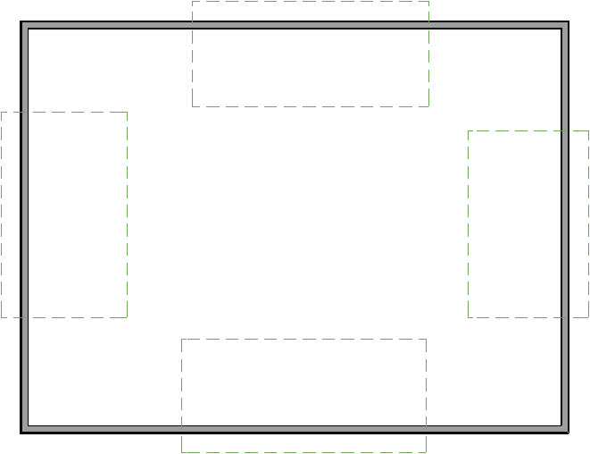
- Click on the side of one of the roof planes to select it. Verify that you have the correct edge selected, click the Join Roof Planes edit tool, and then click the adjacent roof plane to join them at an angle.
- Repeat for the remaining roof planes.
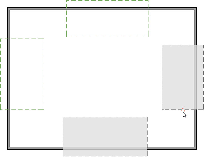
- Now, connect the ridge of the upper and lower roof planes using the Join Roof Planes edit tool.
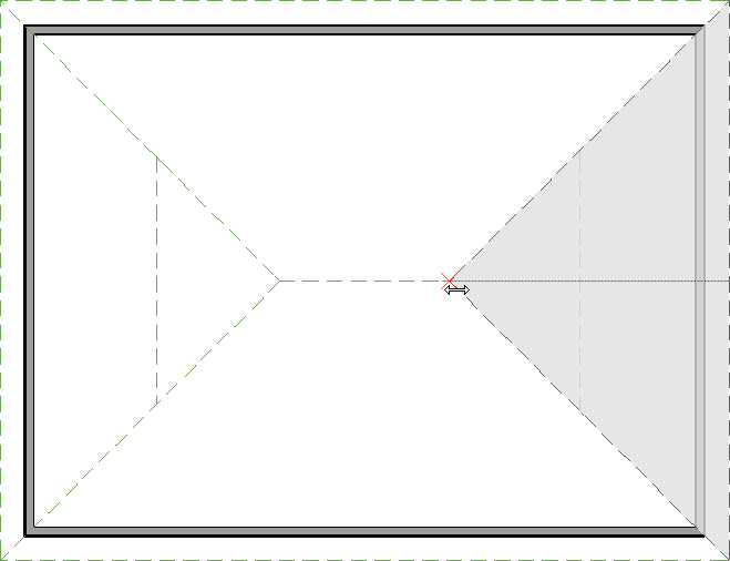
- To connect the smaller side roof planes simply drag its edit handle until it snaps to the intersection.
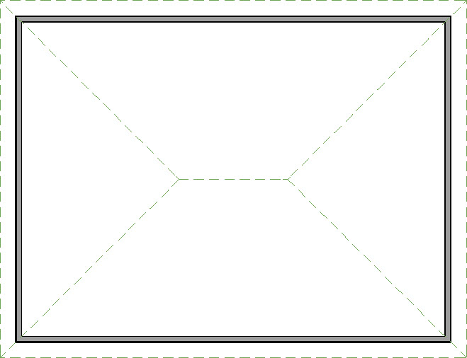
- Select 3D> Create Perspective View> Full Overview to see that we now have a completed hip roof.
MORE INFORMATION
More information on Automatic vs. Manual roof planes can be found within Home Designer Pro by selecting the Help menu and clicking on Launch Help  to display the software's Help menu. Click on the Contents tab and scroll down to the Roofs chapter to review the information further.