Automatically Building the Basic Roof Styles
Pro | Architectural | Suite
QUESTION
How do I use the automatic roof tools to create some of the basic roof styles?
ANSWER
Automatically creating the basic roof styles in Home Designer can be accomplished by making modifications to the Roof panel located in the Wall Specification dialog.
For the purposes of this example, we will begin by creating a basic 30' x 40' enclosed rectangular structure, as shown in the image below.

In this article, we will show you how to create the following roof styles automatically:
HIP
A hip roof has a roof plane built over every exterior wall in the plan that does not have another wall drawn above it, as shown in the image below.

To create a hip roof
- By default, a hip roof will be automatically created on our 30' x 40' structure without making any changes.
- Select Build> Roof> Build Roof
 from the menu.
- On the Roof panel of the Build Roof dialog, the default Pitch (in 12) of the entire roof, the Roof Overhang values, as well as other settings can be set.
- Check the Auto Rebuild Roofs box to enable the program to automatically rebuild the roof whenever a change is made that affects the generation of roofs, such as changes to exterior walls or ceiling heights.
If you want to rebuild the roof a single time instead of enabling Auto Rebuild Roofs, you can check the Build Roof Planes box in Home Designer 2026 and newer, as well as in Home Designer Pro 2025 and prior, or simply click OK in Home Designer Suite and Home Designer Architectural, as mentioned in Step 6 below.
- Access the Materials panel to change the default roof material, as well set the material for that of other roof aspects, such as the gutters.
- Make any other desired changes, then click OK build the roof with the specified settings.
The floor plan view of a standard hip roof will look like the image below.

GABLE
If a wall does not have a roof plane bearing on it, then it's likely a gable wall.

To create a gable roof
To create a basic gable style roof, we need to tell the program to not build a hip roof plane over the two 30' walls.
- Use the Select Objects
 tool to select the left 30' wall, then click on the Open Object
  edit tool.
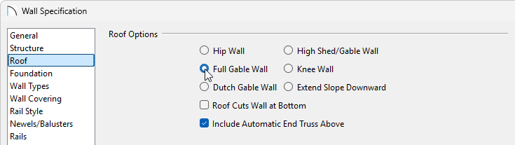
- On the Roof panel of the Wall Specification dialog that displays, select the Full Gable Wall option, then click OK.
- Perform the same procedure on the right 30' wall.
- If you have Auto Rebuild Roofs enabled in the Build Roof dialog, then your plan will update automatically; otherwise, select Build> Roof> Build Roof to display the Build Roof dialog, check the Build Roof Planes box, if available, then click OK to rebuild the roof.
The floor plan view of a standard gable roof will look like the image below. We have indicated the two walls that should be defined as Full Gable Walls to create this roof style.

OFFSET GABLE
An offset gable roof is a type of gable roof with different pitches on each of the two roof planes and a ridge that is offset from the building's center line.

To create an offset gable roof
This roof style can be created by assigning a different pitch to the two roof planes.
- Specify both the left and right walls to be Full Gable Walls using the instructions in the section above.
- Use the Select Objects tool to select the bottom 40' wall, then click on the Open Object edit tool.
- On the Roof panel of the Wall Specification dialog that displays, change the Pitch value to be larger than the rest of the roof, such as 12", then click OK.

-
Open the upper 40' wall, and on the Roof panel, change the Pitch to be a lower value, such as 2", then click OK.
- If you have Auto Rebuild Roofs enabled in the Build Roof dialog, then your plan will update automatically; otherwise, select Build> Roof> Build Roof to display the Build Roof dialog, check the Build Roof Planes box, if available, then click OK to rebuild the roof.
The floor plan view of an offset gable roof will look like the image below. We have specified the lower horizontal wall to have a steeper pitch than the upper horizontal wall.

DUTCH GABLE
A dutch gable, sometimes called a dutch-hip, is a combination of hip and gable roof styles in which a gable is located at the end of the ridge, at the top of a hip roof plane.

To create a dutch gable roof
- Use the Select Objects tool to select the left 30' wall, then click on the Open Object edit tool.
- On the Roof panel of the Wall Specification dialog that displays:
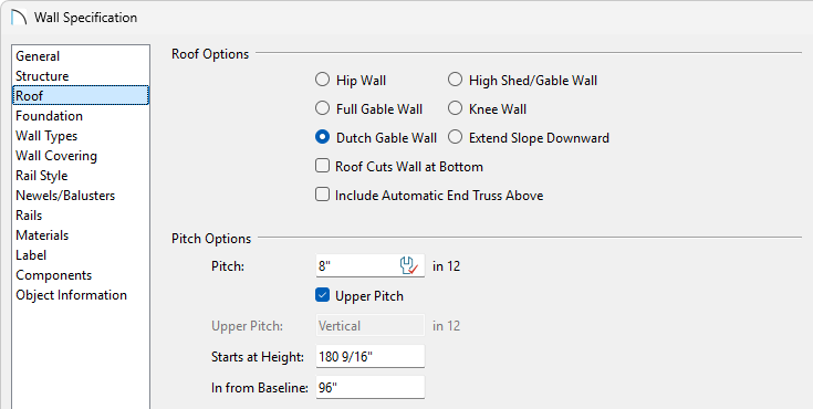
- Select the Dutch Gable Wall option.
- Set either the Start at Height or In From Baseline value.
In this example, we specified an In From Baseline value of 96".
- Click OK to apply these changes and close the dialog.
- Select the Dutch Gable Wall option.
- Perform the same procedure on the right 30' wall.
- If you have Auto Rebuild Roofs enabled in the Build Roof dialog, then your plan will update automatically; otherwise, select Build> Roof> Build Roof to display the Build Roof dialog, check the Build Roof Planes box, if available, then click OK to rebuild the roof.
The floor plan view of a dutch gable roof will look like the image below. We have specified the left and right vertical walls to be Dutch Gable Walls and have set the In From Baseline distance to be 96.

SHED
A shed roof is a single, sloping roof plane.

To create a shed roof
First, we need to tell the program to not build a hip roof plane over the two 30' walls in our plan, set one wall to be a high shed/gable wall, and we will also lower the pitch on the roof so it's not so steep.
- Use the Select Objects tool to select the left 30' wall to select it, then click on the Open Object edit tool.
- On the Roof panel of the Wall Specification dialog that displays, select the Full Gable Wall option, then click OK.
- Perform the same procedure on the right 30' wall.
- Use the Select Objects tool to select the upper 40' horizontal wall and click on the Open Object edit tool.
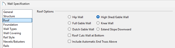
- On the Roof panel, select the High Shed/Gable Wall option, then click OK.
-
Open the lower 40' wall, and on the Roof panel, change the Pitch to be a lower value, such as 2" or 4", then click OK.
- If you have Auto Rebuild Roofs enabled in the Build Roof dialog, then your plan will update automatically; otherwise, select Build> Roof> Build Roof to display the Build Roof dialog, check the Build Roof Planes box, if available, then click OK to rebuild the roof.
The floor plan view of a standard shed roof will look like the image below with a single roof plane. We have indicated the two vertical walls to be defined as Full Gable Walls, and the upper horizontal wall to be defined as a High Shed/Gable Wall.

GAMBREL
A gambrel, or barn style, roof has two pitches on each side of the ridge. The first (lower) pitch on either side is steeper than the pitch near the ridge.

To create a gambrel roof
To create a basic gambrel roof, we need to tell the program to not build a hip roof plane over the two 30' walls in our plan, as well as to set the appropriate lower and upper pitches for the two horizontal 40' walls.
- Use the Select Objects tool to select the left 30' wall to select it, and click on the Open Object edit tool.
- On the Roof panel of the Wall Specification dialog that displays, select the Full Gable Wall option, then click OK.
- Perform the same procedure on the right 30' wall.
- Use the Select Objects tool to select the upper 40' wall and click on the Open Object edit tool.
- On the Roof panel of the Wall Specification dialog that displays:

- Specify the Pitch as 24" in 12.
- Place a check in the Upper Pitch box and set its pitch as 6" in 12.
- Change the In From Baseline value to 60" so that the second pitch will begin 5' in from the top plate. The Start at Height value will adjust automatically based on the other values entered.
- Click OK to apply these changes and close the dialog.
- Specify the Pitch as 24" in 12.
- Perform the same procedure on the lower 40' horizontal wall.
- If desired, experiment with alternate pitches and overhangs. Also, try varying the height at which the second pitch begins so that you can see the effect it has on your gambrel roof design.
- If you have Auto Rebuild Roofs enabled in the Build Roof dialog, then your plan will update automatically; otherwise, select Build> Roof> Build Roof to display the Build Roof dialog, check the Build Roof Planes box, if available, then click OK to rebuild the roof.
The floor plan view of a standard gambrel roof will look like the image below. We have indicated the two vertical walls to be defined as Full Gable Walls, and the two horizontal walls to have an Upper and Lower Pitch, as well as an In From Baseline distance.

GULLWING
A gullwing style roof has two pitches on either side of the ridge, where the first pitch is shallower than the second.

To create a gullwing roof
First, we will need to tell the program to not build a hip roof plane over the two 30' walls in our plan as well as to set the appropriate lower and upper pitches for the two 40' walls.
- Use the Select Objects tool to select the left 30' wall to select it, and click on the Open Object edit tool.
- On the Roof panel of the Wall Specification dialog that displays, select the Full Gable Wall option, then click OK.
- Perform the same procedure on the right 30' wall.
- Use the Select Objects tool to select the upper 40' wall and click on the Open Object edit tool.
- On the Roof panel of the Wall Specification dialog that displays:
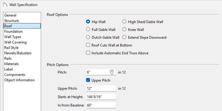
- Specify the Pitch as 6" in 12.
- Place a check in the Upper box and set its pitch as 12" in 12. It's important that the upper pitch is steeper than the standard pitch to create this roof style.
- Change the In From Baseline value to 60" so that the second pitch will begin 5' above the top plate.
- Click OK to apply these changes and close the dialog.
- Specify the Pitch as 6" in 12.
- Perform the same procedure on the remaining 40' wall.
- If desired, experiment with alternate pitches and overhangs. Also, try varying the height at which the second pitch begins so that you can see the effect it has on your gull wing roof design.
- If you have Auto Rebuild Roofs enabled in the Build Roof dialog, then your plan will update automatically; otherwise, select Build> Roof> Build Roof to display the Build Roof dialog, check the Build Roof Planes box, if available, then click OK to rebuild the roof.
The floor plan view of a standard gull roof will look like the image below. We have indicated the two vertical walls to be defined as Full Gable Walls, and the two horizontal walls to have an Upper and Lower Pitch, as well as an In From Baseline distance.
Notice that in floor plan view, this roof style can look identical to the gambrel roof, so it's important to verify that you have your upper and lower pitches set correctly, and verify with a camera view.

HALF-HIP
A half-hip roof has two gable ends, but at the top of each gable is a small hip that extends to the ridge. It is a combination of gable and hip roof styles in which a hip roof plane builds upward from a partial gable wall.

To create a half-hip roof
We need to tell the program to not build a hip roof plane over the two 30' walls.
- Use the Select Objects tool to select the left 30' wall to select it, and click on the Open Object edit tool.
- On the Roof panel of the Wall Specification dialog that displays:
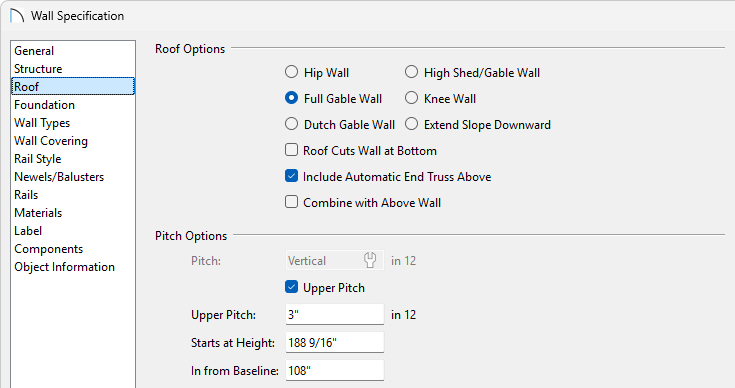
- Select the Full Gable Wall option.
- Check the box next to Upper pitch, then specify the Upper pitch as 3" in 12
- Set the In from Baseline value to 108".
- Click OK to apply these changes and close the dialog.
- Select the Full Gable Wall option.
- Perform the same procedure on the right 30' wall.
- If you have Auto Rebuild Roofs enabled in the Build Roof dialog, then your plan will update automatically; otherwise, select Build> Roof> Build Roof to display the Build Roof dialog, check the Build Roof Planes box, if available, then click OK to rebuild the roof.
The floor plan view of a standard half-hip roof will look like the image below. We have indicated the two vertical walls to be defined as Full Gable Walls, and have set the same walls to have an Upper Pitch and an In From Baseline distance.

MANSARD
A mansard roof is a hip roof with two slopes on the roof sections above each of the four walls. The second slope begins at the same height above each wall. The upper slope is usually quite gentle and the lower slope, much steeper.

To create a mansard roof
To create a mansard style roof, we will need to make several adjustments to the roof settings for all of the walls.
- Use the Select Objects tool to select the left 30' wall to select it, and click on the Open Object edit tool.
- On the Roof panel of the Wall Specification dialog that displays:

- Specify a Pitch of 24".
- Place a check next to the Upper Pitch box and enter a value of 1/4".
- Change the In from Baseline value to 60".
- Click OK to apply these changes and close the dialog.
- Specify a Pitch of 24".
- Perform the same procedure on the remaining three walls.
- If you have Auto Rebuild Roofs enabled in the Build Roof dialog, then your plan will update automatically; otherwise, select Build> Roof> Build Roof to display the Build Roof dialog, check the Build Roof Planes box, if available, then click OK to rebuild the roof.
The floor plan view of a standard mansard roof will look like the image below. We have indicated all four walls should have their Upper and Lower Pitches defined, along with an In From Baseline distance.

MORE INFORMATION
All of these instructions and more can be located within your software by selecting the Help menu and clicking on Launch Help ![]() to launch the software's searchable resources.
to launch the software's searchable resources.
You may also want to review some of the other articles within the Knowledge Base, as well as the online Training Videos, to learn more about how to create custom roof styles.