Customizing Terrain Slope and Modifying Landscaping
Pro | Architectural | Suite
QUESTION
How do I customize the slope of my terrain, as well as add landscaping features?

ANSWER
Once a Terrain Perimeter has been established, the slope can be customized using the Elevation Data tools. The Terrain Feature tools can then be used to create outdoor spaces for a wide variety of uses, from decorative plantings and improved privacy, to areas for entertaining or playing games.
In this article, we will use these tools to design a sloped golf hole, from tee to green.
To create sloped terrain
A good starting point for any landscaping project is to first create the desired terrain contours. Once in place, level, raised, and lowered areas can be specified for plants, privacy, recreation, or other uses.
- In a blank plan, select Terrain> Create Terrain Perimeter
 from the menu to create a Terrain Perimeter.
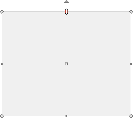
- You can change the shape of the Terrain Perimeter by selecting it, then clicking and dragging any of the edit handles that display along its edges and at each corner.
To move an edge, click on that edge to select it, then click the edit handle that displays at the point where you clicked.
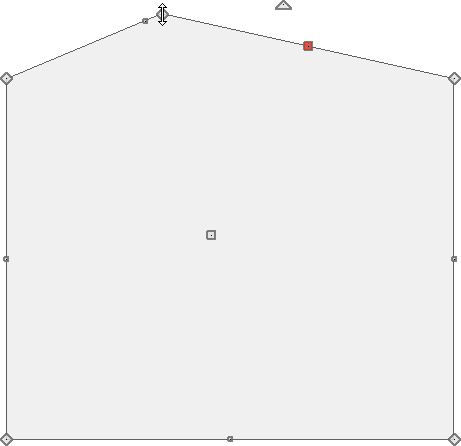
- If you would like to add additional edges to the Terrain Perimeter:
- Click on an edge that you would like to break into two separate segments to select it.
- Click the Add Break
 edit button.
- Click along the selected edge to place a break, or new corner at that location.
- You can now click and drag the new corner edit handle.
- Click on an edge that you would like to break into two separate segments to select it.
- If you would like a perimeter edge to be curved, click on that edge and then click the Change Line/Arc
 edit button.
- The radius of a curved edge can be adjusted by clicking and dragging the triangular edit handle that displays near where the line is clicked.
- To change a curved edge back to a straight edge, select it and then click the Change Line/Arc edit button once more.
- The radius of a curved edge can be adjusted by clicking and dragging the triangular edit handle that displays near where the line is clicked.
- When the Terrain Perimeter is the desired shape and size, select Terrain> Elevation Data> Elevation Line
 from the menu, then click and drag in the drawing area to create your first elevation line.
- Once the elevation line is drawn, it can be moved and its length adjusted as needed by selecting and using the edit handles.
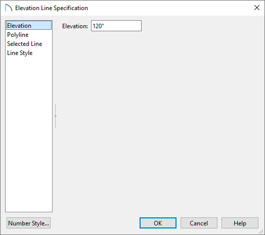
- With the elevation line selected, click the Open Object
 edit button to open the Elevation Line Specification dialog and specify the desired Elevation on the Elevation panel.
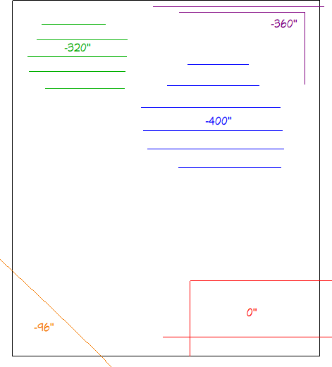
- To create a simple, continuous slope in your plan, at least two elevation lines with different Elevation values are needed, as shown in the example below:
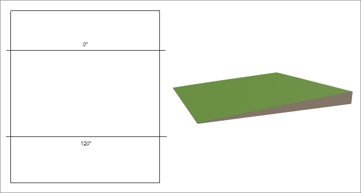
- Additional elevation lines can be added to control slope, steepness, and direction.
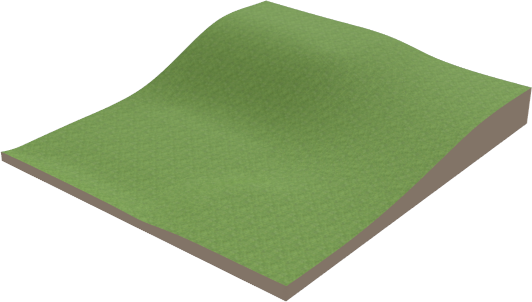
- To create a simple, continuous slope in your plan, at least two elevation lines with different Elevation values are needed, as shown in the example below:
Elevation Regions can also be used to specify the elevation of a specific area; instead of being line-based, they are polyline-based and can be edited much the way a Terrain Perimeter can, by using the various edit handles and edit toolbar buttons. To create an Elevation Region, navigate to Terrain> Elevation Data> Elevation Region ![]() from the menu, then click and drag to draw a rectangular elevation region. In this example, regions are used to create tee boxes.
from the menu, then click and drag to draw a rectangular elevation region. In this example, regions are used to create tee boxes.
Note: The program automatically assigns a single elevation value to an Elevation Region based on the average elevation at its location, however, the region can be opened to specification and this value can be altered manually. Elevation Regions can be helpful for creating level areas for patios or playing outdoor games.
To create varying ground covers using terrain features
Terrain features follow the contours of your terrain and allow you to apply different materials to specific areas of your plan. They can also be assigned heights relative to the terrain they are drawn on.
- Select Terrain> Feature> Rectangular Feature
 from the menu, then click and drag in the drawing area to create a rectangular feature.
- Other terrain features, such as driveways and sidewalks, garden beds, and ponds can also be created by clicking and dragging.
- Garden beds and ponds are spline-based and can be created by clicking and dragging or by simply clicking in the drawing area.
- Other terrain features, such as driveways and sidewalks, garden beds, and ponds can also be created by clicking and dragging.
- Once created, terrain features can be edited the way a Terrain Perimeter or Elevation Region can, by using the edit handles or edit toolbar buttons.
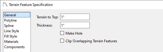
- Terrain features can have their Terrain to Top and Thickness specified on the General panel of the Terrain Feature Specification dialog.
- Terrain features can also be assigned various materials, such as gravel, concrete, or other ground cover.
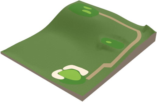
- In this example, the tee boxes are defined with different grass materials found in the Core Catalogs located within the Library Browser
 . Separate grass regions can also be used for this process, which can be accessed by navigating to Terrain> Grass Region
  . These regions give you the ability to specify additional grass parameters, such as blade density, minimum and maximum heights, and more.
- The bunkers are assigned a sand material to represent the light colored sand typically used on golf courses.
- The path uses a sandstone material.
- In this example, the tee boxes are defined with different grass materials found in the Core Catalogs located within the Library Browser
When your terrain is in place, you can complete your design by adding trees, shrubs and other plants from the Library Browser, as well as furnishings, fixtures, or images of people, animals, or other objects from Bonus Catalogs.