Building a Manual Dormer in Home Designer Pro
The information in this article applies to:

QUESTION
How do I create a manual dormer in Home Designer Pro?
ANSWER
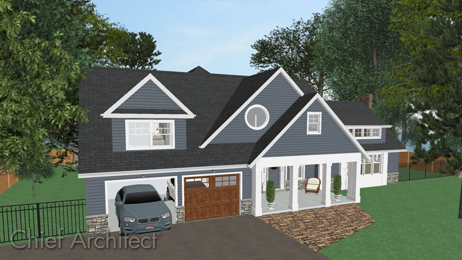
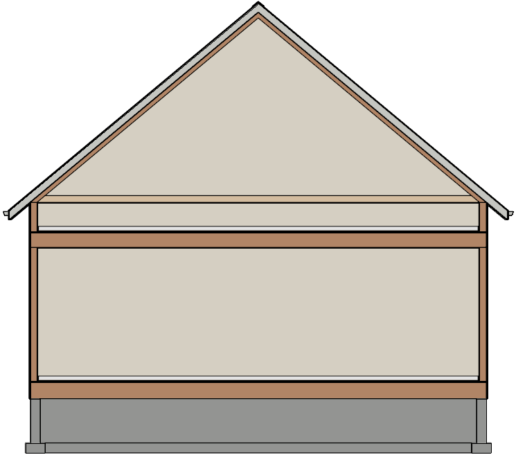
There are several methods for creating dormers in Home Designer Pro, including using the Auto Dormer or Auto Floating Dormers tools, automatic roof generation, and manual roof tools. In this article, the manual method for creating a dormer will be used in a basic 40' x 30' rectangular structure, with a 10 in 12 pitch gable roof sitting low on the second story walls, as demonstrated in the Cross Section image below.
If you are unfamiliar with the tools to create this type of structure, please begin with KB-00358: Automatically Building a One and a Half Story Roof, which is linked in the Related Articles section at the bottom of this article.
To create the dormer walls
- In a floor plan view, go up to Floor 2, select Build> Wall> Straight Interior Wall
 , then click and drag out an interior wall approximately 8' from the exterior wall.
- Use the Select Objects
 tool to select this interior wall, and click on the Open Object
  edit tool to display the Wall Specification dialog.
- On the Roof panel, select Knee Wall under the Roof Options section and click OK.
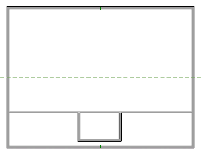
- Next, select Build> Wall> Straight Exterior Wall
 and use this tool to create a room that will become the dormer, as shown in the image below.
- Select the interior wall using Select Objects
 , then use the Add Break
  edit tool to place break points where the two dormer walls intersect the interior knee wall.
- Now, use the Select Objects
 tool to select the center wall segment created by the breaks, then click the Delete
  edit tool, or the Delete key on your keyboard, to remove it.
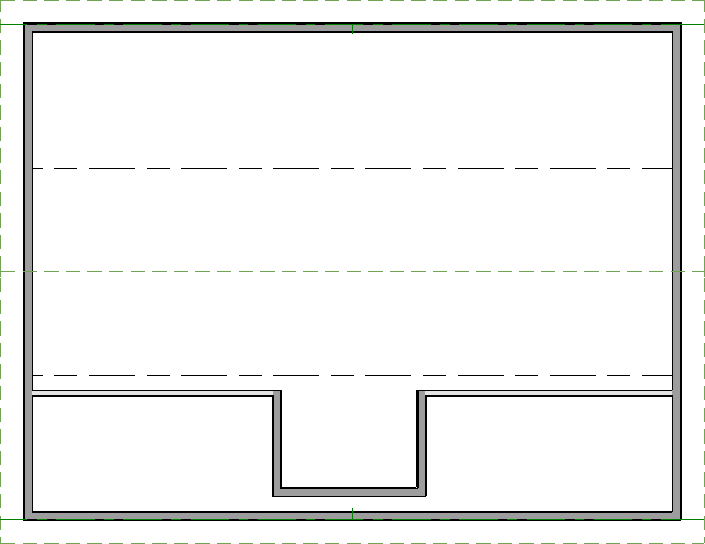
Now that the dormer walls are in place, a hole in the roof plane will be needed to allow the walls to come through in order to create the dormer.
To create a hole in the roof
- From the menu, select Build> Roof> Skylight
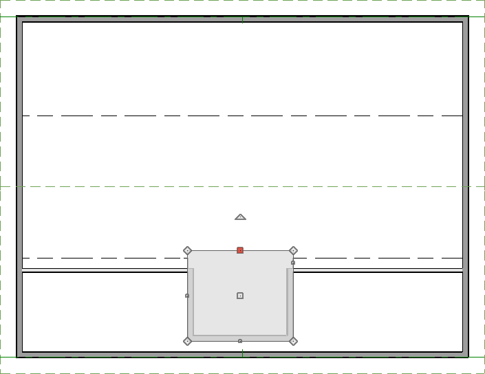
 and either click to place a skylight polyline in the dormer area, or click and drag a skylight polyline around the dormer.
- Click to select the skylight polyline and use the square edit handles on each edge of the polyline to ensure that the front and sides of the polyline snap flush to the exterior of your dormer walls.
- With the skylight still selected, click Open Object
 to open the Roof Hole/Skylight Specification dialog.
- On the General panel, uncheck Skylight, and under Inside Hole Rim, select the radio button next to Plumb Sides.
- Click OK to apply these changes.
To draw the dormer roof planes
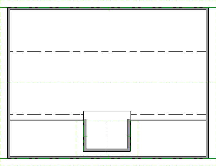
- Select Build> Roof> Roof Plane
 and draw two roof planes over the side dormer walls to form a gable condition.
If prompted with a Set Baseline Height dialog box, asking "Where would you like the new roof plane baseline to be located?", select "Over wall top".
- To ensure a proper ridge, use the Select Objects
 tool to select the ridge line edge of one of the newly drawn roof planes, click on the Join Roof Planes
  edit tool, then click on the ridge edge of the second roof plane to join the two roof planes together.
- Selecting each roof plane, be sure to grab the front, gable eave edge line and pull it out, creating the eave overhang.
To adjust the shape of the roof hole
- Using the Select Objects
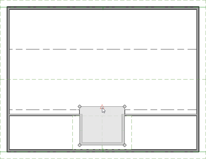
 tool, click to select the Roof Hole polyline, click the Add Break
  edit tool, then click to place a break in the center of the top edge of the polyline, breaking this edge into two segments that can be joined with the roof planes on either side.
- Using the Select Objects
 tool again, select the top edge of the left dormer roof plane, click the Join Roof Planes
  edit tool, then click on the left segment of the Roof Hole polyline.
The roof plane will angle its top edge in order to meet with the hole, which will cut and angle one side to join flush with the roof plane.
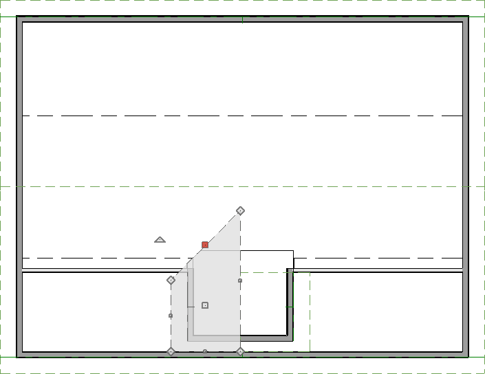
- Repeat this process for the right dormer roof plane.
The remaining top edge of the roof hole will move and angle in order to meet flush with the reshaped roof plane, finalizing the dormer.
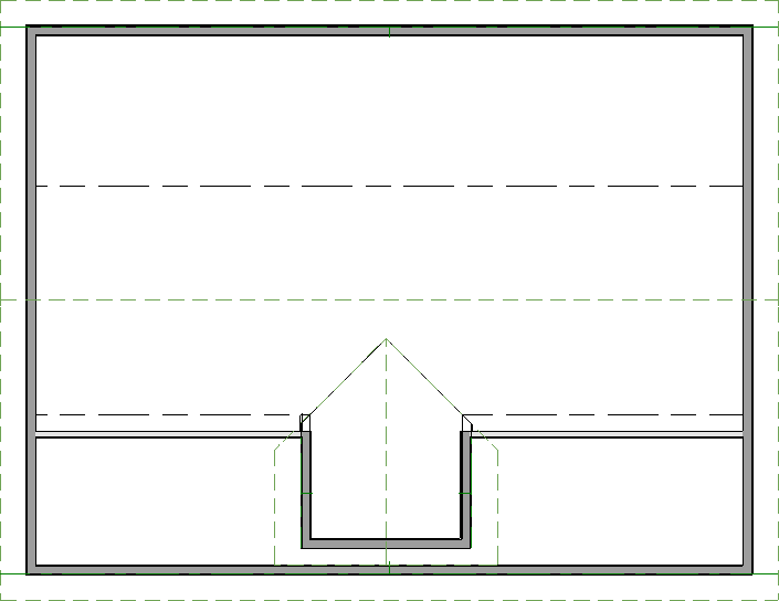
If you receive a Warning dialog stating "Hole in roof, slab, countertop, or terrain object is not completely contained.", this occurs when the roof planes are too high. This means that the joined ridgeline is generating above the main roof ridge, which can be caused by a wide dormer. Either decrease the width of the dormer being created, manually lower the roof plane baselines or lower the dormer roof pitch.
